Groundwater Flow Systems
Groundwater Flow Systems Report
A study was conducted by the Bureau of Rural Sciences (Coram, J.,et al. 1999) as a part of the National Land and Water Resources Audit. This established a national technical framework for dryland salinity management which defines hydrogeological characteristics of a catchment's groundwater flow system, which is defined as;
· Local flow systems
· Intermediate flow systems
· Regional flow systems
In practice groundwater flow systems may contain one or more elements of these. For instance, the basalt plains will contain local and intermediate groundwater flow cells that superimpose on top of the regional system.
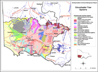
 Groundwater Flow Systems | Eighteen Groundwater Flow Systems have been delineated in the Glenelg-Hopkins CMA region based on the model put forward by the National Land and Water Resources Audit. This overview map provided here shows the generalised distribution of these Groundwater Flow Systems. The detailed report associated with this mapping is available here. |
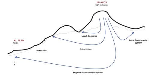
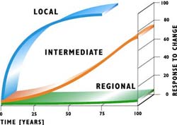
Local flow systems respond rapidly to increased groundwater recharge. These systems can also respond relatively rapidly to salinity management practices, and afford opportunities for dryland salinity mitigation through alternative land management practices. Local groundwater flow systems have recharge and discharge areas within a few kilometres of one another. They tend to occur within individual subcatchments in areas of higher relief, such as foothills to ranges. These systems exhibit dryland salinity within a decade or so of clearing. The Dundas Tablelands are an example of a local flow system in the Glenelg-Hopkins region.
Groundwater flow systems, local, intermediate and regional:

Intermediate flow systems have a greater storage capacity and permeability than local systems and take longer to ‘fill’ in response to increased recharge. The extent and responsiveness of these groundwater systems offer much greater challenges for dryland salinity control. Intermediate groundwater flow systems are intermediate in extent between local and regional systems, generally occurring within individual catchments but also sometimes flowing between smaller subcatchments. They tend to occur in valleys, and typically occur over a horizontal extent of five to ten kilometres. The Fractured Palaeozoic bedrock systems are an example of intermediate flow systems in the Glenelg-Hopkins region.
Regional groundwater flow systems have a high storage capacity and high permeability, and take a much longer time period to develop groundwater discharge than local or intermediate flow systems. Saline groundwater discharge may not occur for more than a hundred years after agricultural development. Regional systems occur on a scale that is so large as to make farm-based catchment management options impractical. Salinity mitigation in these systems will require widespread community action related to issues of common concern, as well as engineering measures to protect high value assets and infrastructure, together with the adoption of living with salt strategies. Regional groundwater flow systems are characterised by laterally extensive aquifers, which may be thicker than 300 metres, and recharge and discharge areas separated by distances of fifty or more kilometres. They occur in areas of low relief such as alluvial plains. The aquifers in regional systems are usually wholly or partly confined, and can be overlain by local and intermediate flow systems. The time for groundwater discharge to occur following post clearing increases in groundwater recharge may be as great as 100 years. The Basalt Plains are an example of a regional groundwater flow system in the Glenelg-Hopkins region.
Catchment characterisation numerical model that describes the response of different groundwater flow systems (local, intermediate or regional) to changes in land use:

Source: NDSP & MDBC


