
Tunnel Initiation and Development
Tunnel Erosion Home | Distribution of Tunnel Erosion | Reclamation of Tunnelled Land | Conclusions | References
The mechanisms causing tunnel initiation in northeastern Victoria (Downes, 1946; 1949) are also illustrated with examples of landforms from Costerfield, and have been discussed in detail by Boucher (1990). Milton (1971) proposed a variety of sub-types of sapping, tunnelling and tunnel-sapping which were essentially based on the permeability of the affected materials. Sheet erosion has often been a precursor to the onset of tunnelling and, consequently, a sparse grass cover remains. The bare patches of ground have been subjected to the mechanical action of rainsplash, which gives a crusted appearance to the often poorly-structured, hard-setting A horizon, reducing its permeability and producing increased surface runoff.
Tunnel initiation and development at Caniambo, northeastern Victoria (Boucher, 1990)
| The schematic model of tunnel erosion depicted above was adapted from an early version included in Landcare Note - Tunnel Erosion on the topic (Cummings, 1999), so as to reflect the affected land at Caniambo. The relevant soils data are presented in the following table. The cross-section illustrates an example of continuous gradient tunnelling whereby the translocated sediment debouches on the soil surface downslope, rather than through a free face (Boucher, 1990). In this case, tunnel initiation took place when surface runoff collected in a depression created by the removal of a tree stump, and flowed along the path of an `old root line'. Other points of enhanced water entry include natural zones of high infiltration, soil cracks, rabbit scrapes and burrows and contour furrows (Boucher, 1990). Downes (1946) noted that seasonal subsoil desiccation cracking was essential to tunnel initiation but only for providing an exit for discharge in soils where the permeability is very slow. | 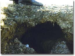 The subsoil has been eroded leaving a tunnel into which humans, stock and agricultural equipment may fall near Costerfield. Photograph: Stuart Boucher. |
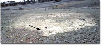 A view of a debris fan looking downslope towards a subcatchment gully near Costerfield. The wristwatch marked with an arrow near the point of exfiltration is approximately 4 cm in diameter. Photograph:Stuart Boucher. | The first evidence of tunnelling is the deposition of soil translocated from upslope, moving under an hydraulic head. The coarser particles form a mound near the outlet whilst the clay fraction is transported further in suspension. As the tunnel conducts higher discharge a distinct debris fan forms, smothering vegetation in the immediate vicinity. At this stage, much damage has already been done. |
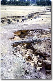
| A different type of tunnel exit occurs when tunnelflow is channelled directly into a subcatchment gully. In this case, the translocated sediment merges with other material conducted through the gully and the debris fan is not always conspicuous. At a later stage of development the surface soil is undermined to the point that it collapses into the enlarging tunnel forming a sinkhole. This subsidence could occur due to small rainfall events once a critical span width of the channel is reached, as well as in response to severe rainstorms, especially where the subsoil is highly erodible. In areas where the surface soil structure has been protected by vegetative growth, sinkhole formation is likely to take place earlier than when the A horizons are more compact and rigid. The sinkhole in the foreground of the first plate presented in this article is approximately 1.2 m in diameter and they range up to 2.4 m in depth at this site. |  Turbid tunnelflow draining into the subcatchment gully following a storm in November, 1983: near Costerfield. Photograph: Stuart Boucher. |
 An example of a natural bridge near Costerfield is approximately 1.5 m in wide. Photograph: Stuart Boucher. | In the areas studied by Downes (1946), the average A horizon depth is between 10 cm and 15 cm and the highly resistant, poorly-structured zones leave natural bridges between sinkholes. Considerable force or weight is required to break these residual landforms. The critical surface span width prior to the natural collapse of these bridges into tunnels near Caniambo was between 1.5 m and 1.8 m. Tunnels extended up to 120 m in length near Caniambo, whilst the longest tunnel branch measured at the Costerfield site was 234 m. A gully produced by the merging of sinkholes is the ultimate evolutionary outcome of tunnel erosion with respect to landform development (Boucher, 1990). However, two mechanisms have been proposed to account for tunnel initiation linked to the prior existence of a free face (ie. a gully wall) in southern New South Wales (Crouch, 1976; Crouch et al., 1986) and they may also operate in Victoria. For example, precipitation and surface runoff may enter the surface soil near the bank, and move into the gully through cracks which provide a ready exit for concentrated throughflow. The steep hydraulic gradient enables dispersible clay to be eroded. The second mechanism is that of hillslope seepage concentrating in a relatively permeable layer in the wall, facilitating headward tunnel extension. |
Critical Soil Properties which affect Tunnel Erosion in Victoria
As mentioned earlier, the incidence of tunnel erosion in Victoria has been most frequent on sodic duplex soils. A soil profile provided by Downes (1946; 1949) for Caniambo is presented in the following table.
Profile Characteristics | Horizon | Horizon Depth (") | Horizon Depth (cm)a | Texture | pH 1:5 | Sum of Major Cations | ESPb |
Iron-impregnated chips; | A1 | 0-4 | 0-10 | Loam | 6.6 | 9.6 | 3.1 |
Iron-impregnated chips; | A2 | 4-6 | 10-15 | Loam | 6.9 | na | na |
Small, nutty when dry & plastic and sticky when wet | B1 B1 B1 | 6-10 10-17 17-36 | 15-25 25-43 43-91 | Clay Clay Clay | 7.4 7.5 7.8 | 12.2 na 26.4 | 9.4 na 19.6 |
Ordovician & Silurian slates, sandstones, shales & quartzites | BC | 36-72 | 91-183 | Clay | 5.1 | na | na |
| Legend a inserted by the author. b calculated as ESP [m.e. 100g] = Exchangeable Na [100] na not available. |
M. Imhof (pers. comm.) classified the above profile as Solodised Solonetz and Solodic (Stace et al., 1968), Dy 3.42 (Northcote, 1979) and Grey Sodosol (Isbell, 1996). An important characteristic of this type of soil profile relates partly to the much higher clay content of the B horizon relative to the A horizon. Two main factors govern the tendency of the clay fraction to disperse spontaneously upon wetting; soil sodicity and the level of soluble salts in the pore solution. The clay particles of the upper part of the B1 horizon at Caniambo are termed `sodic' as the Exchangeable Sodium Percentage (ESP) is between 6 and 14, whilst the lower part of the subsoil is `strongly sodic' because the ESP exceeds 15 (Northcote and Skene, 1972). These subsoils have also often been strongly leached (i.e. they contain low levels of soluble salts) so that the slaking of soil aggregates into microaggregates is followed by spontaneous clay dispersion. Downes (1946) noted that the samples of the B horizon dispersed readily in water. Consequently, the presence of nonsaline-sodic soils can be a major contributing factor to the loss of aggregate stability and rapid soil erosion by water. It should be noted that rills, gullies and tunnels can also form on non-dispersive soils, although an example of the latter case in NSW required special conditions (R.J. Crouch, pers. comm.).
© State of Victoria (Agriculture Victoria) 1996 - 2025.

This work, Victorian Resources Online, is licensed under a Creative Commons Attribution 4.0 licence. You are free to re-use the work under that licence, on the condition that you credit the State of Victoria (Agriculture Victoria) as author, indicate if changes were made and comply with the other licence terms.
The licence does not apply to ‘branding’ or some ‘images or photographs’ that may be owned by third parties. We ask you to seek prior approval to use images using the VRO feedback form. Access to higher quality images can also be provided on request.
This page was last updated on 22/02/2021.