Step 4.3.1 - What planning issues do I need to consider?
Back to - Step 4.3 - What needs to be considered in the planning, design, cost and management of subsurface drip irrigation (SDI)?
There are many aspects that should be considered during the planning of an SDI system. Planning considerations focus on the following questions.
Step 4.3.1.1 - What are the general advantages and disadvantages of SDI systems?
Every irrigation system has advantages and limitations and no irrigation system is appropriate under all environmental conditions. The advantages and limitations of SDI systems are described in Table 1, and Table 3.1 (Step 3).
Table 1: Advantages and disadvantages of SDI systems
Advantages of SDI systems
| Disadvantages of SDI systems
|
Step 4.3.1.2 - What are the key components of SDI systems?
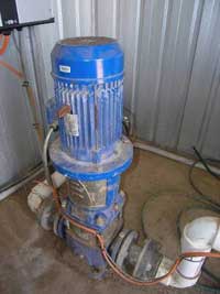
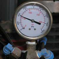
The main components of SDI systems are pump, filter, pressure gauge, flow meter, main and sub-main, valves, drip tape and emitters (Figure 1). These components are necessary to properly manage and maintain the system. The descriptions here are a guideline only as the specific site and system conditions for your installation must be considered when designing your system.
Pump
Pump characteristic curves (Figure 3) are provided by manufacturers to show the performance of pumps with respect to pressure (head), flow rate, speed and power. Characteristic curves can be of two types (a) a constant speed with different impeller diameters, or (b) variable speed with constant impeller diameter. In order to know the appropriate performance of the pump you should know the pump duty, which is the required flow rate and pressure of the pump. For example in Figure 3b, pump duty is 9.75 litres per second at 2300 rpm and 60 m head for an efficiency of 70%. Pump suppliers can help you in the selection of the right pump for your system.
(a)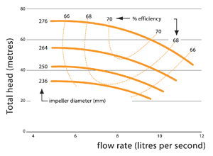 | (b)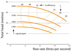 |
Pressure gauges
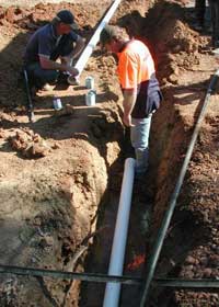
Main and sub-main
Drip tape and emitters
Drip tape is made of polyethylene. Usually a neoprene grommet, polyethylene barb adapter, clamps and polyethylene connector (60-90 cm long) are used to connect the sub-main to each drip tape (Figure 6). Emitters are located on the drip tape at a regular spacing. There are many types of emitters available in the market, such as vortex, diaphragm, adjustable flow, dripline, pressure compensating and non pressure compensating. Emitters come in a variety of sizes and flow rates, and should match your crop water requirement, the requirements of the site and the hydraulic characteristics of the soil. Low flow rate emitters may not adequately irrigate the crop, while high flow rate emitters may cause water losses in the form of deep drainage and/or runoff. A well designed system will have a uniform flow rate across the field. Where there are large elevation changes in a field or long lateral lengths, pressure compensating emitters or division into sub-blocks should be considered for better performance.
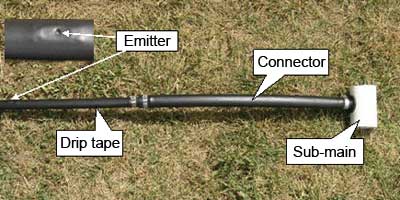
Figure 6. Drip tape connected to sub-main line
Flow meters
The installation of a flow meter in the main line is necessary for good irrigation management. The flow meter is installed in the main line downstream of the pump to measure the volume of water used per irrigation and for the season (Figure 7a). Flow meters for this purpose usually measure flow in megalitres (ML) or cubic metre (m3). Multiplying m3 by 0.001 will convert flow rate to ML. Usually one flow meter is enough in the main line if the whole system is managed as one block but if the field is managed as sub-blocks then separate flow meters can be used to measure and manage irrigation of sub-areas (Figure 7b).
(a)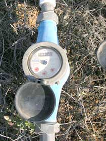 | (b)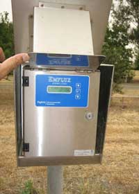 |
Filter
| The filter is a critical part of SDI systems and increases the life expectancy of the system. Filters remove physical, chemical and biological impurities (Section 4.3.1.7) and prevent the blockage of the drip tapes and emitters. If filters are not installed, small sand particles can create wear and tear to different parts of the system. Particles greater than 300 µm in size cannot pass through emitters and will cause clogging, whilst particles greater than 100 µm can lodge in emitter labyrinth passages. There are many types of filter systems available such as screen, cartridge, media, disk (Figure 8) and centrifugal filters. The selection of the most appropriate filter depends on your water quality and budget. Surface water generally requires a greater degree of filtration than good quality groundwater. Sometimes a combination of filters gives better results than using a single type of filter. Filters will block up as sediment accumulates, so backwash cycles are required to remove accumulated material. Good SDI equipment suppliers can provide guidance on selection of the best filters for your specific requirements. | 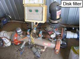 Figure 8. Disk filter installed in SDI system |
Valves
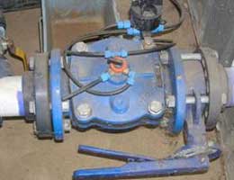
Valves play important role in controlling water pressure and flow rate to optimise system performance and facilitate management. Some of the valves used in SDI systems are described below.
Pressure regulating valve
Control valve
Control valves are used to turn water on and off in the system. Depending on the layout, there may be one control valve for the whole field or separate valves for each su-block.
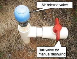
Air release valve
Backflow prevention valve
Backflow prevention valves are used between the irrigation water source and the pump to avoid contamination of water sources from fertiliser, herbicides, pesticides, acid or chlorination that may have been added to the irrigation system.
Flushing valve
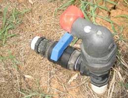
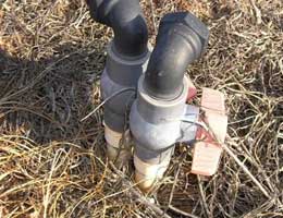
The main purpose of the flushing valves (Figure 11) is to enable flushing of the system in order to remove sediments and other contaminants which can block the system. Flushing flow is directed through the drip tapes to the sub-main and out though the flushing valves. For effective flushing the water velocity in the drip tapes should be higher than normally required for irrigation. The size of the flushing valve required will depend on the area to be flushed. Generally, manually operated flushing valves are used. It is recommended that all automatic or independent control valves be capable of manual operation.
 |  |
Fertiliser unit
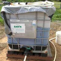
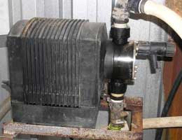
To apply liquid fertiliser with irrigation water (fertigation), a fertiliser unit needs to be attached to the system. It consists of a fertiliser tank (Figure 12a), supply pipe, fertiliser pump (Figure 12b) and control valves. Be aware that SDI irrigation manufacturers may recommend specific fertilisers for their systems, and to avoid disputes it may be prudent to either use products that are recommended or check with the system supplier.
| (a) | (b) | |
 |  |
Further information
Queensland Department of Environment and Resource Management - Sub-surface drip irrigation: System components (external link)
Step 4.3.1.3 - What shape and area of land can be irrigated?
SDI systems can be implemented fairly flexibly with respect to field shape and size. Indeed, SDI may have particular application on areas of potentially productive land that are too difficult to set up for either surface or centre pivot irrigation because of irregular shape, topographic relief, trees or infrastructure. Limitations on layout are generally related to impacts on system operating pressure uniformity and flow rates, which ideally should not vary by more than about 10 percent. Irregular layouts are likely to be more expensive to design and install because of the requirement for proportionally greater lengths of sub-main lines and more complex plumbing. Long runs of drip lines should be avoided because of friction losses in the drip line, which impact on flow rate uniformity.
Further information
Queensland Department of Environment and Resource Management - Sub-surface drip irrigation: System design (external link)
Step 4.3.1.4 - Can undulating land be irrigated?
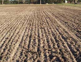
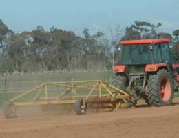
Land leveling is not as critical with SDI systems as it is with surface irrigation. However, increased undulation can increase the design complexity so major undulations should be removed and the field levelled (Figure 13) if feasible. Soil ripping is important to improve rooting depth and soil drainage, and cross ripping will improve the lateral movement of water and irrigation uniformity. With substantial variation in topography it may be more economical to divide the field and manage the irrigation of each part separately. Pressure compensating emitters, which are designed to reduce the effect on emitter flow rate of pressure changes in dripper lines, should be used on undulating sites.
Given the investment required to install SDI, you should ensure that the site has good surface drainage to avoid production losses from inundation or waterlogging after heavy rainfall.
| (a) | (b) | |
 |  |
Further information
Queensland Department of Environment and Resource Management - Sub-surface drip irrigation: Installation (external link)
Step 4.3.1.5 - What soil types can be irrigated?
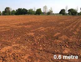
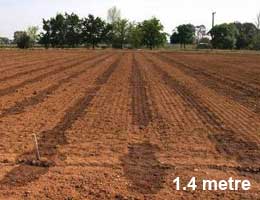
For pasture production in northern Victoria, SDI technology works best on duplex soils featuring a strong texture contrast down the soil profile, typically consisting of a relatively well drained or pervious loam or sandy loam topsoil (A-horizon) with a fairly abrupt texture change to a not so well drained or low permeability medium to heavy clay soil (B-horizon). The low permeable B-horizon soil improves the lateral movement of water in the A-horizon. In light textured soils without a clay subsoil, deep drainage can be substantial and much closer drip tape spacing is required to ensure adequate irrigation of the areas between dripper lines and to avoid substantial water losses to deep drainage (Figure 14).
SDI can also be used on heavy cracking clays but there can be problems with soil shrinkage and swelling, associated constriction of tapes and high longitudinal pressures associated with cohesion along the drip line. Information of soil types in the Shepparton region can be found in Section 2.2.1.
 |  |
Further information
For further information see the Information Note - Small Farm: water infiltration and drainage of soils
Step 4.3.1.6 - What are the water supply issues?
Drip systems typically wet a small volume of soil per emitter and the required flow rate for the whole system is generally less than that required for border-check systems. However, drip systems are irrigated more frequently than other irrigation systems, so a continuous water supply is necessary for irrigation management. The total water requirement for the coming season can be estimated from the average of previous years’ evapotranspiration. Because SDI systems need frequent irrigations, you should investigate placing a repeating order with your water authority rather than placing a separate order for each irrigation event.
In the Goulburn Murray Irrigation District of northern Victoria, direct pumping from a supply channel is the simplest way to supply water to your SDI system, however approval is required from Goulburn-Murray Water (G-MW). Discussion with the G-MW is important to ensure that they can supply the required amount of water. An alternative option may be to pump from an on-site storage dam or to use groundwater. However the ground water quality should be tested to ensure the water is fit for irrigation.
Step 4.3.1.7 - What are the water quality issues?
The good quality irrigation water is important for the soil and crop health as well as system longevity. The physical, chemical and biological impurities of irrigation water can affect SDI performance by clogging and damaging the system. A laboratory analysis of source water can provide information on water quality.
Physical impurities
Physical impurities can be suspended soil particles, grass and roots. It is recommended that a representative sample of the water should be tested for turbidity (sediment levels) to gauge the amount of particles in suspension. A test of irrigation supply channel, river and bore water turbidity was carried out as part of a SDI study on pasture at Dookie in northern Victoria (Figure 15). The particle size analysis showed that the water samples to be very different in terms of particulates. The Broken River water showed a significant amount (approximately 75%) of particulates greater than 100 µm in size. The irrigation supply channel water also showed a significant amount of >100 µm particles (approximately 40%). The bore water was clearly of better quality in terms of particulates and only contained a small fraction over 100 µm. The laboratory analysis showed that particulates <100 µm in size are not problematic to performance and are easily cleared through the dripper. The study concluded that water filtration was required particularly for river and channel water prior to use in SDI systems.
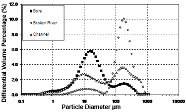
Figure 15. Particle size in groundwater, Broken river and channel water (Dassanayake et al. 2009). Graph courtesy of Melbourne Uni and Gardiner Foundation.
Chemical impurities
Chemical impurities in supply water can also clog SDI systems, and acid treatment is necessary to remove precipitate contaminants such as white calcium carbonate or reddish brown iron oxide. The application of acid solution into the irrigation water can break up scale deposits (Reich et al. 2009). The acid most commonly used in SDI systems is sulfuric acid. Use of acid at higher concentration than recommended can damage SDI systems, while too low concentration may not fully clear blockages.
The use of acids is dangerous and chemical protocols need to be followed for their handling, storage and deployment. It is essential to read and follow instructions and precautionary measures when using acids and other chemicals. For further information contact SDI service providers and equipment suppliers.
Biological impurities
Biological clogging can be from bacteria, algae or other vegetable matter. Injecting a mild chlorine solution can help clean bacterial slime accumulations inside drip tape and emitters. At low concentration (1 to 5 ppm) chlorine can kill bacteria and remove iron oxidation.
The potential for clogging of the system by physical, chemical and biological impurities is given in Table 2.
Table 2. Potential for clogging of SDI by irrigation water (Pitts et al. 1990)
| Factor | Symbol | Units | Minor | Moderate | Severe |
| pH | < 7.0 | 7 - 8 | > 8.0 | ||
| Bicarbonate | HCO3 | meq/L | < 2.0 | > 2.0 | > 2.0 |
| Iron | Fe | mg/L | < 0.2 | 0.2 - 1.5 | > 1.5 |
| Manganese | Mn | mg/L | < 0.1 | 0.1 - 1.5 | > 1.5 |
| Hydrogen sulphide | H2S | mg/L | < 0.2 | 0.2 - 2.0 | > 2.0 |
| Total dissolved solids | TDS | mg/L | < 500 | 500 - 2000 | > 2000 |
| Suspended solids | mg/L | < 50 | 50 - 100 | > 100 | |
| Bacteria count | No./ML | < 10, 000 | 10, 000 – 50, 000 | > 50, 000 |
Further information
'Section Step' 4.3.1.8
Information Note - Measuring the salinity of water
Information Note - Testing and interpretation of salinity and pH
Queensland Department of Environment and Resource Management - Sub-surface drip irrigation: System maintenance (external link)
Step 4.3.1.8 - Can I use saline groundwater for irrigation?
Salinity in the southern Murray Darling Basin is dominated by sodium chloride (NaCl). Salinity adversely affects soil health, degrades soil structure and reduces soil biological activity. Salinity reduces the capacity of plants to take up water, and in higher concentrations is both toxic to plants and affects the availability of nutrients such as K, Mg, N and P. Table 3 summarises recommended irrigation water salinity concentration for surface irrigation of forage species in the Shepparton Irrigation Region. In the absence of adequate rainfall for leaching there is a risk that salt could rapidly accumulate in the topsoil of SDI fields, so guidelines for surface irrigation need to be used with caution when considering SDI systems. Given the investment required to establish SDI systems and in consequence the need to produce high yielding, high value crops from these systems, it would usually make sense to use poor quality water.
| EC units: 1000 EC = 1000 μS/cm = 1 dS/m = 640 ppm = 1 mmhos/cm |
Table 3. Recommended electrical conductivity of irrigation water for forage species (DPI, 2006)
| Species | Applied irrigation water (EC) | Comments |
| Sensitive plants Clover (white, red, cluster, suckling and subterranean) | Up to 800 | Suitable for use with all crops. Above 800 EC sensitive plants will suffer some yield loss. |
| Moderately-sensitive plant Balansa clover, Persian clover, strawberry clover and lucern | 800-1500 | Sensitive plants have increasingly reduced growth. Moderately-tolerant plants should suffer little yield loss with good management at the lower end of this range. At the upper end, some yield loss occurs. |
| Moderately-tolerant plants Berseem clover, sorghum, tall fescue, phalaris, perennial ryegrass, cocksfoot, wheat and paspalum | 1500-3000 | Moderately sensitive plants will suffer increased yield loss. Moderately-tolerant plants should suffer little yield loss with good management at the lower end of the of this range. At the upper end of some yield loss occurs. |
| Tolerant plants Tall wheatgrass, puccinellia, bermuda grass, barley (grain) | 3000-5000 | Moderately tolerant plants will suffer increased yield decline. Only tolerant plants should be grown with very good irrigation/soil management. Towards the top end of this range some yield decline will occur for some of the tolerant plants. |
Further information
Information Note - Reusing saline groundwater safely - strategies to reduce risk
Information Note - Using saline groundwater in the Shepparton Irrigation Region
Step 4.3.1.9 - Do I need a drainage system?
Good surface and subsurface drainage systems provide the means for managing the productivity impacts of surface inundation and high watertables. Unlike surface irrigation systems, which require good surface drainage in order to operate efficiently, SDI systems do not generate runoff. However significant runoff can occur after rainfall. Rainfall is also the primary driver of the shallow groundwater systems of northern Victoria. So good surface drainage with connection to the regional surface drainage system and options for controlling shallow watertables with groundwater pumping are both important factors in managing climate risk.
Step 4.3.1.10 - What are my catchment obligations?
There are a number of off-farm issues that have to be considered before irrigation development can commence. These issues are discussed in detail in Section 2.2.11.
Step 4.3.1.11 - What are the filtration and flushing requirements of the system?
Laboratory analysis of the irrigation water can help in the selection of filters. Better quality water can reduce the capital cost involved for filtration. Despite good filtration, flushing of SDI drip lines is essential. Particles less than 100 µm can remain in drip lines and can accumulate so these particles need to be purged from drip lines regularly. The frequency of flushing is dictated by the quality of water, the more turbid the water supply the more frequently the lines will need to be flushed. The relatively high water requirements of pastures and fodder crops generally demand more flushing because the particles in water are likely to accumulate faster, so filter backwash cycles are likely to be more frequent for pasture applications compared with horticultural and viticultural applications.
Further information
Queensland Department of Environment and Resource Management - Sub-surface drip irrigation: System maintenance (external link).
Step 4.3.1.12 - Can I grow other crops with the same setup?
A well designed, installed and managed SDI system should last at least a decade, so given the changes that the irrigation sector, and the dairy industry in particular, have seen in the past decade in northern Victoria, it would be prudent to consider potential alternative crops when designing an SDI system. Crop water requirement and rooting depth (Table 4) are key factors that need to be considered when planning an alternative crop on an existing SDI system. The large initial investment cost of SDI systems requires high yield from a high value crop for the system to be viable. Discussion with DPI agronomy staff and SDI service providers and suppliers may help with the development of an adaptable design.
Further information
Information Note - Small Farm: Pasture establishment (PDF - 46 KB)
Table 4. Range of effective rooting depth for different crops (Allen et al. 1998)
| Crop | Rooting depth (m) |
| Broccoli | 0.4 - 0.6 |
| Cabbage | 0.5 - 0.8 |
| Cauliflower | 0.4 - 0.7 |
| Lettuce | 0.3 - 0.5 |
| Tomato | 0.7 - 1.5 |
| Cucumber | 0.7 - 1.2 |
| Potato | 0.4 - 0.6 |
| Barley, Oats, Spring wheat | 1.0 - 1.5 |
| Winter wheat | 1.5 - 1.8 |
| Maize | 0.8 - 1.7 |
| Millet | 1.0 - 1.2 |
| Sorghum | 1.0 - 1.2 |
| Lucerne - for hay | 1.0 - 2.0 |
| Lucerne for seed | 1.0 - 3.0 |
| Clover hay, Berseem | 0.6 - 0.9 |
| Rye grass hay | 0.6 - 1.0 |
| Grazing pasture | 0.5 - 1.5 |
| Bermuda | 1.0 - 1.5 |

