Gully Reclamation Techniques
Gully Erosion Home | Distribution of Gully Erosion | Gully Initiation & Development | Conclusions | References
Gully Reclamation Techniques
Various techniques used to control gully erosion around the world have been discussed elsewhere (e.g. Bennett 1939; Morgan 1986; Hudson 1995). Apart from the work of Milton (1971), there appears to be a lack of detailed published information on methods of gully reclamation in Victoria, and the range of measures adopted by the Soil Conservation Service of NSW (now part of the Department of Land and Water Conservation) was reviewed by Ford et al. (1993). The approach to rehabilitation is site-specific and depends upon the relative importance of the mechanisms involved (e.g. surface and/or subsurface flow in relation to soil erodibility) and, consequently, the costs of inputs. Sargeant (pers. comm.) noted that the high monetary cost of transforming deep gullies into stable drainage lines is a major disincentive to rehabilitation and, given a long period of time, will tend to stabilize and revegetate of their own accord and continue to provide a habitat for numerous indigenous species which would otherwise disappear from the local environment. However, when considering this option, the many impacts of leaving the channel to develop need to be taken into account (see Gully Erosion in Victoria).
|  A head at McHugh's Gully Photograph: Smyth (1982). |
In contrast, a higher rate of water use by improved pasture species means that the size of earthworks and erosion-control structures can be minimized (as runoff within the affected area is reduced) with a concomitant increase in productivity (Department of Conservation, Forests and Lands, 1985). Tree cover (see Reclamation of Tunnelled Land) also improves the aesthetic value of the land and provides shade and shelter for grazing stock. A list of trees recommended for use in gully stabilization in Victoria was presented by Zallar (1980). Subsurface and groundwater flows can be intercepted by deep rooted trees, groundwater pumping and deep tile drains, although further research is required on this topic (I. J. Sargeant, pers. comm.). If dispersive clays related to soil sodicity are present and tunnels are located in the gully head(s) and/or walls, chemical compounds may be required to help stabilize the soil structure (see Reclamation of Tunnelled Land). Milton (1971) observed that there was no entirely satisfactory procedure for gully heads where deep sapping and tunnelling were present and that structures can fail for a variety of reasons.
Gullies can be filled by soil, shaped or be modified by a variety of structures.
- Graham (1984) reported that it is unusual to fill gullies greater than 3 m in depth owing to the associated cost of earthworks. He also stated that for shallower gullies, especially those located in drainage lines, the surrounding topsoil is removed and stockpiled nearby, enabling the subsoil to be pushed into the channel and the immediate area smoothed to requirements. The valuable topsoil (Watkins, 1981) is then replaced to enhance pasture or crop growth. Surplus rock was used to partially fill a gully near Gunnedah (Angel, 1981). Rosewell et al. (1991) noted that whereas gully filling in cropping land can increase the area allocated to production, the costs on grazing land are often difficult to justify, and the objective is largely to inhibit further gully development.
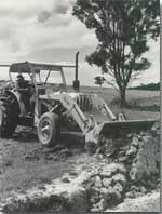
An example of gully filling in the Eppalock catchment. The area involved was later worked with a chisel plough and sown to improved pasture.
Photograph: Department of Conservation, Forests and Lands (1985).
- The cross-sectional shape of shallow gullies can also be modified by using a bulldozer to lower both the head and sidewalls to a more stable angle, and may need a flume to safely conduct subsequent surface water to the reclaimed gully floor (Graham, 1984). These structures may be grassed (Watkins, 1981) or made of concrete (Graham, 1984). Moulded fibreglass was used to make an inlet apron and chute to control gullying of a graded bank channel (Jackson, 1981).
| Harris (pers. comm.) recalled that prior to treatment, this gully near Costerfield was approximately 200 m long, 6 m wide and between 2.4 m and 2.8 m deep. It was reshaped in the late 1970s and revegetated predominantly with phalaris (Phalaris tuberosa) with some currie cocksfoot (Dactylis glomerata). | 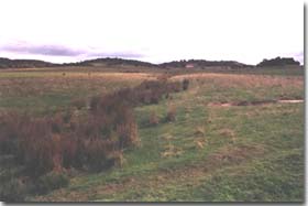 A reshaped gully near Costerfield. Photograph: Stuart Boucher. |
- In cases where filling or reshaping is considered impractical, a typical approach is to construct banks which divert surface runoff and a gully head structure to `drown' the gully head (Rosewell et al., 1991). Graham (1984) mentioned two techniques which inhibit headwall development by diminishing peak discharge and flow frequency. The diversion of surface water away from the gully head is achieved by the use of spillway banks (which conduct flow to either a stable gully or waterway) and a dam constructed upstream of the headwall to limit its advance. On the other hand, a dam may be constructed within the gully so that waterfall erosion cannot take place at the headwall when the dam is full, thus mitigating headward extension. The latter approach allows a larger area of land to be retained for grazing. Sidewalls can be protected by diversion banks.
 | This concrete gully head drop structure near Costerfield is approximately 3 m wide and 2.5 m deep and was constructed in 1989 (N.T.J. Harris, pers. comm.). The apron is submerged and the adjacent scoured floor serves, to some extent, as a stilling pool. Photograph: Stuart Boucher. |
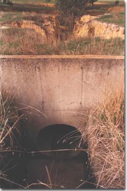 | A concrete gully head pipe structure built near Costerfield in 1978 (N.T.J. Harris, pers. comm.). Photograph: Stuart Boucher. |
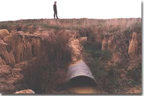 | A downslope view of the structure. Runoff is conducted safely to the gully floor through a pipe which is partially submerged. The person is standing on the concrete ledge shown in the previous photograph. Photograph: Stuart Boucher. |
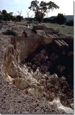 | A different type of concrete gully head pipe structure located in the Parwan Valley. Two people can be seen standing on the collapsed soil material beneath the structure. Smyth (1983) noted that this structure has failed previously because of tunnel erosion. Photograph: Ian Sargeant. |
- Structures can also be built within a gully. A check dam serves to decrease flow velocity upstream and trap sediment in which vegetation may grow (Strom, 1940; Crouch et al., 1987). As a result, the gully is effectively shallower so that it may be filled or shaped at a later date (Graham, 1984), depending on pre-treatment dimensions. Small weirs also confine the velocity of gully flow and its capacity to transport sediment into short sections, so that the stabilized bed gradient can be revegetated (Crouch et al., 1984). Veness (1980) has discussed the reclamation of fluted gullies.


