
LCA Cardinia Shire - Tech Report No. 29 - Appendices
A.1 Total amount of water available to plants
Available Water Capacity (AWC) is a measure of the amount of useable water in the soil for plant growth. It is determined from the difference between the amount of water retained by the soil after drainage (field capacity) and the moisture content of a soil at wilting. (permanent wilting point). There is a reasonable correlation between soil texture and AWC (Salter and Williams 1969) (Table A.1).
Table A.1 Available water capacity of soils.
Range (mm/m) | Average value for calculations (mm/m) | Sands | Sandy loams | Loams | Clay loams | Clays |
76 - 100 | 90 | KS | ||||
101 - 125 | 110 | LKS | KSL | |||
126 - 150 | 130 | S | SC, C | |||
151 - 175 | 160 | CS, LS | SL | L | SCL | |
176 - 200 | 190 | FS | FSL | CL, ZL | ZCL | ZC |
201 - 225 | 210 | LFS |
Note that gravel content of the soil horizons should be taken into account.
Soil horizon | Texture | Depth of horizon (m) | AWC of horizon (mm/m) | Available water in horizon (mm) |
A | SL | 0.15 | 160 | 24 |
B2 | SC | 1.25 | 130 | 143 |
For example, the total amount of water in the worked example above = 167 (Class 2)
A.2 Bearing capacity
Measurements were not taken of bearing capacities.
A.3 Coarse fragment sizes
Gravel: 2 - 60 mm
Cobbles: 60 - 200 mm
Stones: 200 - 600 mm
Boulders: 600 - 2000 mm
A.4 Linear shrinkage
The Linear Shrinkage and depth of solum can replace the value for reactivity of a soil. Reactivity is used in the Australian Standard AS 2870.2 (SAA 1977), and is based on the depth of the clay layer and its shrink-swell capacity. Different areas of Victoria are identified, with 0.6 m depth being a common cut-off mark between two categories.
A.5 Condition of the topsoil
The texture, organic matter content and the size/strength of soil aggregates all influence the general behaviour of soils when subjected to different agricultural land uses and management practices. The lack of knowledge relating the performance of soils to specific attributes does not allow values for the above criteria to be divided into meaningful classes - certainly not the 5-class system used in these land capability rating tables. The concept of "Condition of topsoil" combines the score placed on each criteria to give a total score that is then compared to a 5-class rating, (Table A.2).
Table A2 Rating for topsoil condition.
Criteria | Description | Score |
Texture | Sands | 1 |
Sandy loams | 2 | |
Loams | 5 | |
Clay loams | 4 | |
Clays | 3 | |
Structure (grade) | Apedal, massive | 1 |
Apedal, loose | 2 | |
Weak | 3 | |
Moderate | 4 | |
Strong | 5 | |
Organic matter content (org. C x 1.72) | Very low (<1%) | 1 |
Low (1-2%) | 2 | |
Moderate (2-3%) | ||
High (>3%) | 5 | |
Nutrient status of topsoil (sum of exch. Ca. Mg, K) | Very low <4 meq/100g) | 1 |
Low 4-8 meq/100g) | 2 | |
Moderate (9-18 meq/100g) | 3 | |
High (19-30 meq/100g) | 4 | |
Very high (>30 meq/100g) | 5 | |
Rating for topsoil condition | Class | Total score |
1 | 21-25 | |
2 | 16-20 | |
3 | 11-15 | |
4 | 6-10 | |
5 | 5 |
For profiles with more than one A horizon, i.e. A1 and A2, top soil conditions should be determined separately for each horizon and then averaged.
Nutrient status of topsoil: The topsoil is considered the major source of nutrients for plant growth whereas the subsoil is the more reliable source of moisture. Nutrient status of topsoil = sum of exchangeable base cations (Ca, Mg, K) (Lorimer and Schoknecht 1987).
A.6 Depth to hard rock or impermeable layer
This criterion provides a measure of the effectiveness of the soil profile in filtering the nutrient and bacterial content from the effluent. The Septic Tank Code of Practice (Environment Protection Authority et. al. 1990) requires a depth of at least one metre.
A.7 Depth to seasonal watertable
The Septic Tank Code of Practice (Environment Protection Authority et. al. 1990) requires a minimum of one m depth of unsaturated soil for the proper functioning of effluent disposal trenches. Ideally the groundwater table should be much lower than one m, thereby reducing the risk of a rising groundwater table influencing the effectiveness of the absorption trenches. The risk of surface salting problems also increases when a saline groundwater table rises to within 1 - 1.5 m of the soil surface.
A.8 Depth of topsoil
Topsoil depth is considered during dam construction and is used when measuring the susceptibility of topsoils to erosion (Table A.10). Depth of topsoil influences the quantity of overburden that needs to be scraped clear and kept for spreading back on a dam embankment to establish a grass cover, once the construction is completed.
A.9 Dispersibility
Sustainable land use requires that the soil be able to withstand the physical forces of cultivation and compaction without adverse structural change. Soil aggregate stability can be measured by the Emerson Aggregate Test (Emerson, 1977). In the case of secondary roads, dispersion can significantly effect the condition of the road when slopes are greater than 4%. Because of the close correlation between dispersible soils and high exchangeable sodium percentages in those soils, it is unnecessary to include both criteria in the capability rating table.
A.10 Drainage
This parameter is the combination of several criteria that influence the moisture status of the soil profile, viz slope, subsurface and surface flow, water holding capacity, level of groundwater tables, perched or permanent, and permeability. Only because of its general usage, reasonable definition (McDonald et. al., 1984) and direct relevance to effluent disposal fields, building foundations and secondary roads has this criterion been retained.
A.11 Electrical conductivity
The following correlation in Table A.3 between the electrical conductivity of soil samples taken from the 0 - 50 cm layer of the soil profile and soil salinity has been established.
Table A.3 The effects of soil salting on plant growth.
Class | Severity of salting | E.C. dS/m * | Site characteristics |
1 |
|
| Plant growth unaffected |
2 |
|
| Growth of salt-sensitive plants, eg cereals and clover is restricted |
3 |
|
| Patchy pasture growth; salt-sensitive plants are replaced with species that are more salt-tolerant |
4 |
|
| Small areas of bare ground; surviving plant species have high salt tolerance |
5 |
|
| Large areas of bare ground; highly salt-tolerant plants; trees may be dead or dying |
* NB: 1000 µS/cm = 1 dS/m
A.12 Flooding risk
Building regulations prohibit building on flood-prone land, therefore land with some risk of flooding must be identified. Flooding is unlikely to cause a septic tank to fail, however the risk of polluting the floodwaters with phosphorus, nitrogen and bacterial organisms increases with the number of effluent disposal fields involved. The dilution factor will be dependent on the quantity of floodwater.
Table A.4 Flooding risk.
Risk | Class | Limitation | Condition of flood |
| 1 |
| No flooding |
| 2 |
| Minor inundation No debris Flood return period: annual |
| 3 |
| Broad, slow moving No debris Flood return period: 1 in 20 to 1 in 50 years |
| 4 |
| Broad, slow moving Little debris Flood return period: 1 in 100 years |
| 5 |
| Deep channel, fast flowing Debris carrying Flood return period: 1 in 100 years |
A.13 Length of the growing season
Agricultural production is governed by moisture, temperature and photoperiod (photoperiod is taken to be consistent throughout Victoria).
Length of Growing Season (months) = 12 - (P + T)
P = Number of months where monthly evapotranspiration > average monthly rainfall
T = Number of months where mean monthly
temperature < 6o C
A.14 Number of months per year when average daily rainfall > Ksat
This parameter is included (although it is closely aligned to drainage) to provide an indication from climatic, rather than soil and topographic data, of the period of time each year when effluent absorption trenches might cease to function.
Data required:
* Average monthly rainfall figures.
* Average number of wet days for each month.
* Ksat values.
Assumptions made:
* Evapotranspiration <1 for winter months.
* Winter-early spring months are when problems arise.
* The soil profile is at field capacity.
* Where slope is significant, run-off = run-on.
A.15 Permeability of a soil profile (Ksat)
Permeability is controlled by the least permeable layer of a soil profile and its ability to transmit water. Permeability is independent of climate and surface drainage. The rate at which water moves down through the soil profile is an indicator of the tendency of a soil to saturate, it is an important feature if plant growth is to be maintained in areas where rainfall is spasmodic or unreliable.
Permeability provides a measure of the rate at which a saturated soil profile will conduct water to depth. Ksat measurements may over-estimate the value for the disposal of effluent because the soil macropores are transmitting water, whereas the real situation must take into account the clogging effect of effluent on the bottom of effluent disposal trenches, thereby reducing the rate of water movement into the soil.
The measurement of Ksat often produces quite variable results even between replicates on the same site, so the setting of class limits is difficult and by necessity must be very broad. Estimates of permeability can be made using the features of the least permeable soil horizon if Ksat values are not available, however it should be clearly indicated where estimates have been made (Table A.5).
Table A.5 permeability characteristics of a soil profile.
Estimated permeability | Ksat range (mm/day) | Time taken for saturated soil to drain to field capacity | Soil features |
| Very Slow |
|
| Absence of visible pores |
| Slow |
|
| Some pores visible |
| Moderate |
|
| Clearly visible pores |
| Rapid |
|
| Large, continuous clearly visible pores |
| Very Rapid |
|
| Abundant large pores |
| Excessive |
|
| No restriction to water movement through the soil profile |
A.16 Index for permeability/rainfall
This relationship has been included to take into account the situation where a strongly structured soil with very high permeability would be assessed as having a major limitation. In a dry climate, this would be correct as the soil would be drought-prone most of the year, however in a high rainfall area such a soil may be highly productive. Conversely a soil with low permeability may experience waterlogging for extended periods in a high rainfall area, but store sufficient moisture to extend the average growing season of a low rainfall area. A method of combining permeability and rainfall is shown in Table A.6.
Table A.6 Index for permeability/rainfall.
Permeability | Average annual rainfall (mm/year) | |||||
Estimated | Ksat (mm/day) | < 400 | 400 - 600 | 600 - 800 | 800 - 1000 | > 1000 |
Very Slow | < 10 | High | High | Moderate | Low | Very low |
Slow | 10 - 100 | High | Very high | High | Moderate | Low |
Moderate | 100 - 500 | Moderate | High | Very high | High | Moderate |
Rapid | 500 - 1500 | Low | Moderate | High | Very high | High |
Very Rapid | > 1500 | Very low | Low | Moderate | High | Very high |
A.17 Rock outcrop
This estimate has not been included as a parameter that influences the performance of earthen dams because the parameter, depth to hard rock, is inversely correlated to the proportion of rock outcropping at the soil surface, and is a good surrogate.
A.18 Slope
As the slope increases, so too does the chance of run-on water entering effluent disposal trenches and saturating the system. In addition, run-off of unfiltered effluent is more likely to enter minor drainage depressions and water courses. The increasing incidence of algal blooms in water storages emphasises the need to eliminate the entry of unfiltered effluent into watercourses.
The best ratio of earth moved to water stored in dams occurs on land with slopes between 3-7%. Gentler slopes involve greater expense as the above ratio approaches unity, whereas steeper slopes require higher embankments for proportionally less water stored.
A.19 Susceptibility to gully erosion
No single factor can adequately represent the susceptibility of an area to the gully erosion process. A number of factors are involved and each should be scored independently and then the sum of the scores can be related back to a 5 - class rating (Table A.7).
Table A.7 Susceptibility to gully erosion.
Criteria | Description | Score |
|
| 1 |
| 2 | |
| 3 | |
| 4 | |
| 5 | |
|
| 5 |
| 4 | |
| 3 | |
| 2 | |
| 1 | |
|
| 1 |
| 2 | |
| 3 | |
| 4 | |
| 5 | |
|
| 1 |
fine < 2 mm | 3 | |
| 2 | |
| 1 | |
fine < 2 mm | 4 | |
| 3 | |
| 2 | |
fine < 2 mm | 5 | |
| 3 | |
| 1 | |
| 5 | |
|
| 1 |
| 2 | |
| 2 | |
| 4 | |
| 3 | |
| 5 | |
| 4 | |
| 5 | |
| 4 | |
Rating for susceptibility to gully erosion: | Class | Total score |
| 6 - 10 | |
| 11 - 13 | |
| 14 - 17 | |
| 18 - 20 | |
| 21 - 25 |
Note: The ratings for the Shire of Cardinia have been improved by one rating due to the high growth rate and ground cover during the summer months.
A.20 Susceptibility to slope failure
The instability of slopes in a catchment area of a dam poses a threat to the storage capacity of that dam. Additional costs are also involved if the dam requires regular desludging. This assessment considers that land slips are the result of factors such as soil depth, slope, soil texture, volume of water held in the soil, permeability of the solum and the underlying parent material. Since the quantity of water in a profile is itself a function of soil texture, depth and permeability, the table below is presented as a first attempt to assess the susceptibility of land to slope failure by relating the total amount of water in the soil profile to the slope (Table A.8).
Table A.8 Susceptibility to slope failure.
Slope % | Total amount of water in the soil profile | ||
Low (< 70 mm H20) | Moderate (70-170 mm H20) | High (> 170 mm H20) | |
|
|
|
|
|
|
|
|
|
|
|
|
A.21 Suitability of subsoil for earthen dams
In the building of earthen dams, suitability of subsoil is dependent on the nature of the material, which is represented by the Unified Soil Group classification, and depth of the material. Refer to Table A.9.
Table A.9 Suitability of subsoil for earthen dams.
| Unified soil group of subsoil | |||||
| Depth of Subsoil (m) | SP, SW, GP, GW, Pt, OH, OL | ML, MH | GM, CH, SM | CL | GC, SC |
| Very low | Very low | Very low | Very low | Very low |
| Very low | Low | Moderate | Moderate | Moderate |
| Very low | Moderate | High | High | High |
| Very low | Moderate | High | High | Very high |
A.22 Susceptibility of soil to sheet and rill erosion by water
The following table (Table A.10) has been adapted from Elliott and Leys (1991). The erodibility index for a range of soil properties closely relates to the susceptibility of soils to erosion by water, and in the tables below, the same soil properties have been used (texture, structure grade, topsoil depth and dispersibility (Emerson aggregate test)) and then related to slope to determine a rating for susceptibility. The final rating for susceptibility to sheet/rill erosion is read from Table A.11 once the erodibility of the topsoil and the slope of the area have been assessed.
Table A.10 Erodibility of topsoils.
Soil parameters | Soil Dispersibility | ||||
Texture group (A1) | Structure grade (A1) | Horizon depth (A1 + A2) | Very Low - Low E3(1), E3(2), E4,E5, E6, E7, E8 | Medium - High E3(3), E3(4), E2 | Very High E1 |
|
|
0.2 - 0.4 m > 0.4 m | M L L | ||
|
weakly pedal |
0.2 - 0.4 m > 0.4 m < 0.2 m 0.2 - 0.4 m > 0.4 m | M L L H M M | H M E V | |
|
weakly pedal peds evident |
0.2 - 0.4 m > 0.4 m < 0.2 m 0.2 - 0.4 m > 0.4 m < 0.2 m 0.2 - 0.4 m > 0.4 m | M L L H M M H H H | H M E V E | |
|
weakly pedal peds evident |
0.2 - 0.4 m > 0.4 m < 0.2 m 0.2 - 0.4 m > 0.4 m < 0.2 m 0.2 - 0.4 m > 0.4 m | M L L H M M H H M | H M E V E E | |
|
peds evident highly pedal |
0.2 - 0.4 m > 0.4 m < 0.2 m 0.2 - 0.4 m > 0.4 m < 0.2 m 0.2 - 0.4 m > 0.4 m | H M M M M M H M M | E V V V H H E V V | E E E E E E |
heavy clay |
peds evident highly pedal |
0.2 - 0.4 m > 0.4 m < 0.2 m 0.2 - 0.4 m > 0.4 m < 0.2 m 0.2 - 0.4 m > 0.4 m | M M M H M M H M M | H H H E V V E V V | E V V E E E E E E |
L - Low M - Moderate H - High V - Very high E - Extreme
Table A.11 Susceptibility of soil to sheet and rill erosion.*
Slope % | Topsoil erodibility (from Table A.10) | ||||
Low | Moderate | High | Very high | Extreme | |
| < 1 % |
|
|
|
|
|
| 1 - 3 % |
|
|
|
|
|
| 4 - 10% |
|
|
|
|
|
| 11 - 32% |
|
|
|
|
|
| > 32% |
|
|
|
|
|
*Note: Topsoil erodibility is determined from the texture, structure, depth and dispersibility of the topsoil (Table A.10). The susceptibility of the topsoil to sheet and rill erosion relates to the combined effect of slope and topsoil erodibility (Table A.11).
The ratings for the Shire of Cardinia have been improved by one rating due to the high growth rate and ground cover during the summer months.
A.23 Susceptibility of soil to erosion by wind
The susceptibility of land to wind erosion is a function of soil erodibility, the probability of erosive winds when the soil is dry and the exposure of the land component to wind (Lorimer 1985). Soil erodibility is a very important factor to consider in land capability rating tables (Table A.12).
Table A.12 Soil erodibility.
| Soil type | Rating | |
1 | Surface soil has a strong blocky structure (aggregates > 0.8 mm), or is apedal and cohesive or has a dense layer of stones, rock or gravel |
|
| Surface soil has strong fine structure (aggregates < 0.8 mm) |
| |
| Surface soil has a weak-moderate structure or is apedal and loose |
| |
2 | Surface soils with organic matter > 20% |
|
| Surface soils with organic matter 7 - 20% |
| |
| Surface soils with organic matter < 7% |
| |
3 | Surface soils with the following textures: | |
| Fine-medium sands |
| |
| Loamy sands |
| |
| Sandy loams, silty loams |
| |
| Loams, coarse sands |
| |
| Clay loams |
| |
| Clays |
| |
Note: The ratings for the Shire of Cardinia have been improved by one rating due to the high growth rate and ground cover during the summer months.
A.24 Susceptibility to acidification
Soil acidification is usually observed over time as a decrease in soil pH. It may take place in the topsoil or subsoil. Soil acidification will cause contrasting effects depending upon the initial pH of the soil. In general, soil pH below 4.5 (CaCl2) will cause toxic aluminium and manganese to be released. This causes retarded root growth in plants and may increase leaching of soluble salts and nutrients into groundwater, rivers and streams.
Measurement of susceptibility to acidification for this report is based upon the following table (Table A.13) and analysis of topsoils from each map unit.
Table A.13 Susceptibility of soil to acidification.
Susceptibility | Texture | pH (CaCl2) | Annual rainfall |
Low |
Heavy |
All | > 450mm > 450 mm |
Moderate |
Light |
< 4.5 | > 450 mm > 450 mm |
High |
|
| > 450 mm |
Note: Land management, such as pasture species and stocking rates can contribute to acidification. Organic matter is not used as an indicator for susceptibility as its effects are complex.
APPENDIX B. WORKING TABLES FOR LAND CAPABILITY CLASSES
B.1 Agriculture.
| MAP UNITS | Qa1 | Qa2 | Qa3 | Qa4 | Qa5 | Qa6 | Qa7 | Qa8 | Qa9 | Qa10 | Qa11 | Qa12 | Tvb1 |
| Climate | 2 | 2 | 2 | 2 | 2 | 2 | 2 | 2 | 2 | 2 | 2 | 2 | 2 |
| Topography | 1 | 1 | 1 | 1 | 1 | 1 | 1 | 1 | 1 | 1 | 1 | 1 | 5 |
| Topsoil conditions A1, A2 | 2 | 2 | 1 | 2 | 2 | 1 | 2 | 2 | 2 | 2 | 2 | 1 | 2 |
| Depth of topsoil | 1 | 1 | 1 | 2 | 2 | 1 | 1 | 1 | 2 | 1 | 1 | 1 | 2 |
| Depth to hard rock/pan | 1 | 1 | 1 | 1 | 1 | 1 | 1 | 1 | 1 | 3-4 | 1 | 1 | 1-2 |
| Depth to seasonal watertable | 2 | 2 | 2 | 2 | 2 | 2 | 2 | 2 | 2 | 2 | 2 | 2 | 1 |
| Available water capacity | 1 | 1 | 1 | 1 | 1 | 1 | 2 | 1 | 1 | 3-4 | 1 | 1 | 1 |
| Permeability-rainfall index | 2 | 2 | 3 | 2 | 3 | 3 | 2 | 3 | 3 | 3 | 3 | 3 | 2 |
| Dispersibility of topsoil | 2 | 1-2 | 1 | 1 | 1 | 1 | 2 | 1 | 2 | 1 | 1 | 1 | 2 |
| Gravel/stone/boulder content | 2 | 1 | 1 | 1 | 1 | 1 | 2 | 1 | 2 | 2 | 2 | 1 | 1 |
| Electrical conductivity | 1 | 1 | 1 | 1 | 1 | 1 | 1 | 1-2 | 1 | 1 | 1 | 1 | 1 |
| Susceptibility to sheet erosion | 1 | 1 | 1 | 1 | 2 | 1 | 1 | 2 | 2 | 1 | 1 | 1 | 3 |
| Susceptibility to gully erosion | 2 | 1 | 1 | 1 | 1 | 2 | 2 | 2 | 2 | 1 | 2 | 2 | 2 |
| Susceptibiltiy to wind erosion | 1 | 1 | 1 | 1 | 1 | 1 | 1 | 1 | 1 | 3 | 1 | 1 | 1 |
| MAP UNITS | Tvc1 | Tvd1 | Tve1 | Tvf1 | Tvh1 | Tvb2 | Tvc2 | Tvd2 | Tve2 | Tvf2 | Tsd | Tse | Tsf |
| Climate | 2 | 2 | 2 | 2 | 2 | 2 | 2 | 2 | 2 | 2 | 2 | 2 | 2 |
| Topography | 4 | 3 | 1 | 2 | 2-3 | 5 | 4 | 3 | 1 | 2 | 3 | 2 | 2 |
| Topsoil conditions A1, A2 | 2 | 2 | 2 | 2 | 2 | 2 | 2 | 2 | 2 | 2 | 2 | 2 | 2 |
| Depth of topsoil | 2 | 2 | 1 | 1 | 1 | 2 | 2 | 2 | 1 | 1 | 1 | 1 | 1 |
| Depth to hard rock/pan | 1-2 | 1-2 | 1-2 | 1-2 | 1 | 1-2 | 1-2 | 1-2 | 1-2 | 1-2 | 1 | 2 | 1 |
| Depth to seasonal watertable | 1 | 1 | 1 | 1 | 2 | 1 | 1 | 1 | 1 | 1 | 2 | 2 | 2 |
| Available water capacity | 1 | 1 | 1 | 1 | 1 | 1 | 1 | 1 | 1 | 1 | 1 | 2 | 1 |
| Permeability-rainfall index | 2 | 2 | 2 | 2 | 2 | 2 | 2 | 2 | 2 | 2 | 2 | 2 | 3 |
| Dispersibility of topsoil | 2 | 2 | 2 | 2 | 2 | 2 | 2 | 2 | 2 | 2 | 1 | 2 | 1 |
| Gravel/stone/boulder content | 1 | 1 | 2 | 1 | 1 | 1 | 1 | 1 | 2 | 1 | 3 | 3 | 3 |
| Electrical conductivity | 1 | 1 | 1 | 1 | 1 | 1 | 1 | 1 | 1 | 1 | 1 | 1 | 1 |
| Susceptibility to sheet erosion | 2-3 | 2-3 | 2 | 2-3 | 2-3 | 3-4 | 2-3 | 2-3 | 2 | 3-2 | 2 | 2 | 2 |
| Susceptibility to gully erosion | 2-3 | 2 | 1 | 2 | 2-3 | 2-3 | 2-3 | 2 | 1 | 2 | 2 | 2 | 2 |
| Susceptibiltiy to wind erosion | 1 | 1 | 1 | 1 | 1 | 1 | 1 | 1 | 1 | 1 | 1 | 1 | 1 |
B.1 Agriculture (continued).
| MAP UNITS | Tsg | Tsh | Dga | Dgb | Dgc | Dgd | Dge | Dgf | Dgg | Dgh | Dgi | Ssa | Ssb |
| Climate | 2 | 2 | 2 | 2 | 2 | 2 | 2 | 2 | 2 | 2 | 2 | 2 | 2 |
| Topography | 1 | 1 | 2 | 5 | 4 | 3 | 2 | 2 | 1 | 2 | 1 | 2 | 5 |
| Topsoil conditions A1, A2 | 2 | 2 | 3 | 3 | 3 | 3 | 3 | 4(A12) | 4(A12) | 2 | 2 | 2(A2) | 2(A2) |
| Depth of topsoil | 1 | 1 | 2 | 1 | 1 | 1 | 2 | 2 | 2 | 1 | 1 | 1 | 1 |
| Depth to hard rock/pan | 1 | 1 | 2 | 4 | 2 | 2 | 2 | 2 | 2 | 1 | 1 | 3-4 | 3-4 |
| Depth to seasonal watertable | 2 | 2 | 1 | 1 | 1 | 1 | 1 | 2 | 2 | 5 | 5 | 1 | 1 |
| Available water capacity | 1 | 1 | 2 | 3 | 3 | 3 | 2 | 3 | 3 | 3 | 3 | 3 | 3 |
| Permeability-rainfall index | 3 | 3 | 3 | 3 | 3 | 3 | 4 | 3 | 3 | 4 | 4 | 2 | 2 |
| Dispersibility of topsoil | 1 | 1 | 1 | 1 | 1 | 1 | 1 | 2 | 2 | 3(A2) | 3 | 1 | 1 |
| Gravel/stone/boulder content | 3 | 2 | 4 | 4 | 2 | 3 | 3 | 2 | 2 | 1 | 1 | 3 | 3 |
| Electrical conductivity | 1 | 2 | 1 | 1 | 1 | 1 | 1 | 1 | 1 | 1 | 1 | 1 | 1 |
| Susceptibility to sheet erosion | 1 | 2 | 3 | 4 | 3 | 3 | 2 | 2 | 1 | 2 | 2 | 2 | 4 |
| Susceptibility to gully erosion | 2 | 2 | 3 | 3 | 3 | 3 | 2 | 2 | 1 | 2 | 2 | 2 | 3 |
| Susceptibiltiy to wind erosion | 1 | 1 | 3 | 3 | 3 | 3 | 3 | 2 | 2 | 2 | 2 | 1 | 1 |
| MAP UNITS | Ssc | Ssd | Sse | Ssf | Ssg | Ssh | Ssi | Sma | Smb | Smc | Smd | Smf | Smh |
| Climate | 2 | 2 | 2 | 2 | 2 | 2 | 2 | 2 | 2 | 2 | 2 | 2 | 2 |
| Topography | 4 | 3 | 2 | 2 | 1 | 1 | 1 | 2 | 5 | 4 | 3 | 3 | 2 |
| Topsoil conditions A1, A2 | 3(A2) | 3(A2) | 2(A2) | 3(A2) | 3(A2) | 3(A2) | 3(A2) | 2 | 3 | 2-3 | 2-3 | 2-3 | 2-3 |
| Depth of topsoil | 1 | 1 | 1 | 1 | 1 | 1 | 1 | 2 | 1 | 1 | 1 | 1 | 1 |
| Depth to hard rock/pan | 3-4 | 2-3 | 2 | 2 | 2 | 2 | 2 | 3-4 | 3-4 | 3-4 | 2 | 2 | 2 |
| Depth to seasonal watertable | 1 | 1 | 1 | 1 | 1 | 1 | 1 | 1 | 1 | 1 | 2 | 2 | 3 |
| Available water capacity | 3 | 3 | 3 | 3 | 2 | 2 | 2 | 3 | 3 | 3 | 2 | 2 | 2 |
| Permeability-rainfall index | 2 | 2 | 2 | 2 | 3 | 3 | 3 | 2 | 2 | 2 | 2 | 2 | 2 |
| Dispersibility of topsoil | 1 | 1 | 1 | 1 | 1 | 1 | 1 | 1 | 1 | 1 | 1 | 1 | 1 |
| Gravel/stone/boulder content | 3 | 2 | 3 | 2 | 2 | 2 | 2 | 3 | 3 | 4 | 5 | 5 | 3 |
| Electrical conductivity | 1 | 1 | 1 | 1 | 1 | 1 | 1 | 1 | 1 | 1 | 1 | 1 | 1 |
| Susceptibility to sheet erosion | 3 | 3 | 2 | 2 | 2 | 2 | 2 | 2 | 3 | 3 | 2 | 2 | 2 |
| Susceptibility to gully erosion | 2 | 2 | 2 | 2 | 2 | 2 | 2 | 2 | 2 | 2 | 1 | 2 | 2 |
| Susceptibiltiy to wind erosion | 3 | 3 | 1 | 2 | 2 | 2 | 2 | 2 | 3 | 2 | 3 | 3 | 2 |
B.2 Effluent disposal.
| MAP UNITS | Qa1 | Qa2 | Qa3 | Qa4 | Qa5 | Qa6 | Qa7 | Qa8 | Qa9 | Qa10 | Qa11 | Qa12 | Tvb1 | Tvc1 |
| Slope | 1 | 1 | 1 | 1 | 1 | 1 | 1 | 1 | 1 | 1 | 1 | 1 | 5 | 4 |
| Flooding risk | 2 | 2 | 2 | 2 | 2 | 2 | 2 | 2 | 2 | 2 | 2 | 2 | 1 | 1 |
| Drainage | 5 | 4 | 3 | 3 | 3 | 3 | 3 | 3 | 3 | 3 | 3 | 3 | 2 | 2 |
| Depth to seasonal watertable | 2 | 2 | 2 | 2 | 2 | 2 | 2 | 2 | 2 | 1 | 2 | 2 | 1 | 1 |
| Depth to impermeable layer | 1 | 1 | 1 | 1 | 1 | 1 | 1 | 1 | 1 | 1 | 1 | 1 | 1 | 1 |
| Number of months per year when average rainfall >Ksat | 1 | 1 | 1 | 1 | 1 | 1 | 1 | 1 | 1 | 1 | 1 | 1 | 1 | 1 |
| Permeability | 2 | 2 | 4 | 2 | 3-4 | 4 | 2 | 4 | 4 | 3 | 4 | 4 | 1 | 1 |
| MAP UNITS | Tvd1 | Tve1 | Tvf1 | Tvh1 | Tvb2 | Tvc2 | Tvd2 | Tve2 | Tvf2 | Tvh2 | Tsd | Tse | Tsf |
| Slope | 3 | 1 | 2 | 2-3 | 5 | 4 | 3 | 2 | 2 | 2-3 | 3 | 1-2 | 2 |
| Flooding risk | 1 | 1 | 1 | 1 | 1 | 1 | 1 | 1 | 1 | 1 | 1 | 1 | 2 |
| Drainage | 2 | 2 | 2 | 3 | 2 | 2 | 2 | 2 | 2 | 3 | 2 | 2 | 4 |
| Depth to seasonal watertable | 1 | 1 | 1 | 2 | 1 | 1 | 1 | 1 | 1 | 2 | 1 | 1 | 1 |
| Depth to impermeable layer | 1 | 1 | 1 | 1 | 1 | 1 | 1 | 1 | 1 | 1 | 1 | 1 | 1 |
| Number of months per year when average rainfall >Ksat | 1 | 1 | 1 | 1 | 1 | 1 | 1 | 1 | 1 | 1 | 1 | 1 | 1 |
| Permeability | 1 | 1 | 1 | 2 | 1 | 1 | 1 | 1 | 1 | 2 | 2 | 2 | 4 |
| MAP UNITS | Tsg | Tsh | Dga | Dgb | Dgc | Dgd | Dge | Dgf | Dgg | Dgh | Dgi | Ssa | Ssb |
| Slope | 1 | 1-2 | 3 | 5 | 4 | 3 | 2 | 2 | 1 | 2 | 1 | 2 | 5 |
| Flooding risk | 2 | 3 | 1 | 1 | 1 | 1 | 1 | 1 | 1 | 3 | 3 | 1 | 1 |
| Drainage | 4 | 4 | 3 | 2 | 3 | 4 | 5 | 4 | 4 | 4 | 4 | 2 | 2 |
| Depth to seasonal watertable | 1 | 2 | 1 | 1 | 1 | 1 | 1 | 2 | 3 | 4 | 4 | 1 | 1 |
| Depth to impermeable layer | 1 | 1 | 1 | 4 | 2 | 2 | 2 | 1 | 1 | 1 | 1 | 3-4 | 3-4 |
| Number of months per year when average rainfall >Ksat | 1 | 1 | 1 | 1 | 1 | 1 | 5 | 1 | 1 | 5 | 5 | 1 | 1 |
| Permeability | 4 | 4 | 4-3 | 4 | 4 | 4 | 5 | 4 | 4 | 5 | 5 | 2 | 2 |
B.2 Effluent disposal (continued).
| MAP UNITS | Ssc | Ssd | Sse | Ssf | Ssg | Ssh | Ssi | Sma | Smb | Smc | Smd | Smf | Smh |
| Slope | 4 | 3 | 2 | 2 | 1 | 2 | 1 | 2 | 5 | 4 | 3 | 2 | 2 |
| Flooding risk | 1 | 1 | 1 | 1-2 | 2 | 3 | 3 | 1 | 1 | 1 | 1 | 1 | 3 |
| Drainage | 2 | 2 | 2 | 4 | 4 | 4 | 4 | 2 | 2 | 2 | 3 | 3 | 4 |
| Depth to seasonal watertable | 1 | 1 | 1 | 2 | 2 | 2 | 2 | 1 | 1 | 2 | 2 | 2 | 2 |
| Depth to impermeable layer | 3-4 | 3-4 | 3 | 2 | 2 | 1 | 1 | 3-4 | 3-4 | 3-4 | 2 | 1 | 1 |
| Number of months per year when average rainfall >Ksat | 1 | 1 | 1 | 1 | 1 | 1 | 1 | 1 | 1 | 1 | 1 | 1 | 1 |
| Permeability | 2 | 2 | 2 | 2 | 4 | 4 | 4 | 2 | 4-3 | 2 | 2 | 2 | 2 |
B.3 Farm dams.
| MAP UNITS | Qa1 | Qa2 | Qa3 | Qa4 | Qa5 | Qa6 | Qa7 | Qa8 | Qa9 | Qa10 | Qa11 | Qa12 | Tvb1 |
| Slope | 2 | 1 | 2 | 2 | 2 | 2 | 2 | 2 | 2 | 2 | 2 | 2 | 5 |
| Linear shrinkage | 3 | 3 | 2-3 | 3 | 3 | 3 | 3 | 2 | 3 | 2 | 2 | 3 | 3 |
| Suitability of subsoil | 2 | 2 | 2 | 3 | 2 | 5 | 2 | 2 | 2 | 2 | 3 | 5 | 2 |
| Depth to seasonal watertable | 3 | 3 | 3 | 3 | 3 | 3 | 3 | 3 | 3 | 1-3 | 3 | 3 | 1 |
| Depth to hard rock | 2 | 2 | 2 | 2 | 2 | 2 | 2 | 1 | 2 | 1 | 2 | 2 | 3 |
| Permeability | 3-4 | 4 | 3 | 3-4 | 3 | 3 | 4 | 3 | 3 | 3 | 3 | 3 | 4 |
| Dispersibility of subsoil | 3 | 3 | 3 | 2 | 2-3 | 2 | 2 | 3 | 4 | 2 | 2 | 2 | 3 |
| Susceptibility to slope failure | 2 | 2 | 2 | 2 | 2 | 2 | 2 | 2 | 1 | 2 | 2 | 2 | 5 |
| MAP UNITS | Tvc1 | Tvd1 | Tve1 | Tvf1 | Tvh1 | Tvb2 | Tvc2 | Tvd2 | Tve2 | Tvf2 | Tsd | Tse | Tsf |
| Slope | 5 | 4 | 2 | 1-3 | 3-4 | 5 | 5 | 4 | 2 | 1-3 | 4 | 1 | 1-3 |
| Linear shrinkage | 3 | 3 | 3 | 3 | 3 | 3 | 3 | 3 | 3 | 3 | 3 | 2 | 3 |
| Suitability of subsoil | 2 | 2 | 3 | 3 | 2 | 2 | 2 | 2 | 3 | 3 | 2 | 2 | 2 |
| Depth to seasonal watertable | 1 | 1 | 1 | 1-3 | 3 | 1 | 1 | 1 | 1 | 1-3 | 1 | 1 | 1 |
| Depth to hard rock | 3 | 3 | 3 | 3 | 3 | 3 | 3 | 3 | 3 | 3 | 1 | 4 | 1 |
| Permeability | 4 | 4 | 4 | 4 | 4 | 4 | 4 | 4 | 4 | 4 | 4 | 4 | 3 |
| Dispersibility of subsoil | 3 | 3 | 3 | 3 | 3 | 3 | 3 | 3 | 3 | 3 | 3 | 2 | 3 |
| Susceptibility to slope failure | 4 | 4 | 2 | 2 | 4 | 5 | 4 | 4 | 2 | 2 | 3 | 2 | 2 |
B.3 Farm dams (continued).
| MAP UNITS | Tsg | Tsh | Dga | Dgb | Dgc | Dgd | Dge | Dgf | Dgg | Dgh | Dgi | Ssa | Ssb |
| Slope | 2 | 1 | 3 | 5 | 5 | 4 | 1 | 3 | 2 | 1 | 2 | 1-3 | 5 |
| Linear shrinkage | 3 | 2 | 3 | 3 | 3 | 3 | 3 | 3 | 3 | 3 | 3 | 2 | 2 |
| Suitability of subsoil | 2 | 2 | 5 | 3 | 3 | 3 | 5 | 3 | 3 | 3 | 3 | 3 | 3 |
| Depth to seasonal watertable | 1 | 3 | 3 | 1 | 1 | 1 | 1 | 3 | 3 | 5 | 5 | 1 | 1 |
| Depth to hard rock | 1 | 1 | 4 | 4-3 | 4-3 | 4-3 | 4-3 | 3 | 3 | 3 | 3 | 4-5 | 4-5 |
| Permeability | 3 | 3 | 3 | 3 | 3 | 2 | 2 | 3 | 3 | 2 | 2 | 4 | 4 |
| Dispersibility of subsoil | 3 | 1 | 3 | 3 | 3 | 3 | 3 | 3 | 3 | 5 | 5 | 4 | 4 |
| Susceptibility to slope failure | 2 | 2 | 3 | 4 | 3 | 1 | 1 | 1 | 1 | 1 | 1 | 1 | 4 |
| MAP UNITS | Ssc | Ssd | Sse | Ssf | Ssg | Ssh | Ssi | Sma | Smb | Smc | Smd | Smf | Smh |
| Slope | 5 | 4 | 1 | 1-3 | 2 | 1 | 2 | 1-3 | 5 | 5 | 4 | 1-3 | 1 |
| Linear shrinkage | 3 | 3 | 2 | 3 | 3 | 3 | 3 | 3 | 3 | 2 | 3 | 3 | 2 |
| Suitability of subsoil | 3 | 3 | 3 | 3 | 3 | 3 | 3 | 3 | 3 | 5 | 3 | 3 | 5 |
| Depth to seasonal watertable | 3 | 3 | 1 | 3 | 3 | 3 | 3 | 1 | 1 | 3 | 3 | 3 | 3 |
| Depth to hard rock | 4-5 | 4-5 | 4 | 3 | 3 | 3 | 3 | 5 | 4-5 | 4-5 | 4 | 4 | 4 |
| Permeability | 4 | 4 | 4 | 4 | 3 | 3 | 3 | 3 | 3 | 4 | 4 | 4 | 4 |
| Dispersibility of subsoil | 3 | 3 | 4 | 3 | 3 | 3 | 3 | 5 | 3 | 5 | 2 | 2 | 5 |
| Susceptibility to slope failure | 3 | 3 | 1 | 1 | 1 | 1 | 1 | 1 | 4 | 3 | 4 | 2 | 2 |
B.4 Building foundations, i) slab, ii) stumps.
| MAP UNITS | Qa1 | Qa2 | Qa3 | Qa4 | Qa5 | Qa6 | Qa7 | Qa8 | Qa9 | Qa10 | Qa11 | Qa12 | Tva1 | Tvb1 |
| Slope i), ii) | i)1 ii)1 | i)1 ii)1 | i)1 ii)1 | i)1 ii)1 | i)1 ii)1 | i)1 ii)1 | i)1 ii)1 | i)1 ii)1 | i)1 ii)1 | i)1 ii)1 | i)1 ii)1 | i)1 ii)1 | i)1 ii)1 | i)5 ii)4 |
| Drainage | 5 | 4 | 3 | 3 | 3 | 3 | 3 | 3 | 3 | 3 | 3 | 3 | 2 | 2 |
| Depth to seasonal watertable | 3 | 3 | 3 | 3 | 3 | 2 | 2 | 3 | 2 | 2 | 2 | 2 | 1 | 1 |
| Proportion of stone and boulder | 1 | 1 | 1 | 1 | 1 | 2 | 2 | 1 | 2 | 2 | 2 | 2 | 1 | 1 |
| Depth to hard rock | 1 | 1 | 1 | 1 | 1 | 1 | 1 | 1 | 1 | 1 | 1 | 1 | 1 | 1 |
| Susceptibility to slope failure | 2 | 2 | 2 | 2 | 2 | 2 | 2 | 2 | 2 | 2 | 2 | 2 | 2 | 5 |
| Linear shrinkage | i)2 ii)3 | i)2 ii)3 | i)2 ii)3 | i)2 ii)3 | i)2 ii)3 | i)2 ii)3 | i)2 ii)3 | i)1 ii)2 | i)2 ii)3 | i)1 ii)1 | i)1 ii)2 | i)2 ii)3 | i)2 ii)3 | i)2 ii)3 |
| Flooding risk | 2 | 2 | 2 | 2 | 2 | 2 | 2 | 2 | 2 | 2 | 2 | 2 | 1 | 1 |
B.4 Building foundations, i) slab, ii) stumps (continued).
| MAP UNITS | Tvc1 | Tvd1 | Tve1 | Tvf1 | Tvh1 | Tvb2 | Tvc2 | Tvd2 | Tve2 | Tvf2 | Tsd | Tse | Tsf |
| Slope i), ii) | i)4 ii)3 | i)4 ii)3 | i)2 ii)1 | i)3 ii)2 | i)4 ii)3 | i)5 ii)4 | i)4 ii)3 | i)4 ii)3 | i)2 ii)1 | i)3 ii)2 | i)4 ii)3 | i)2 ii)1 | i)3 ii)2 |
| Drainage | 2 | 2 | 2 | 2 | 3 | 2 | 2 | 2 | 2 | 2 | 2 | 2 | 4 |
| Depth to seasonal watertable | 1 | 1 | 1 | 1 | 3 | 1 | 1 | 1 | 1 | 1 | 2 | 2 | 2 |
| Proportion of stone and boulder | 1 | 1 | 1 | 1 | 1 | 1 | 1 | 1 | 1 | 1 | 3 | 3 | 3 |
| Depth to hard rock | 1 | 1 | 1 | 1 | 1 | 1 | 1 | 1 | 1 | 1 | 1 | 2-1 | 1 |
| Susceptibility to slope failure | 4 | 4 | 2 | 2 | 4 | 5 | 4 | 4 | 2 | 2 | 3 | 2 | 2 |
| Linear shrinkage | i)2 ii)3 | i)2 ii)3 | i)2 ii)3 | i)2 ii)3 | i)2 ii)3 | i)2 ii)3 | i)2 ii)3 | i)2 ii)3 | i)2 ii)3 | i)2 ii)3 | i)2 ii)3 | i)1 ii)2 | i)2 ii)3 |
| Flooding risk | 1 | 1 | 1 | 1 | 1 | 1 | 1 | 1 | 1 | 1 | 1 | 1 | 2 |
| MAP UNITS | Tsg | Tsh | Dga | Dgb | Dgc | Dgd | Dge | Dgf | Dgg | Dgh | Dgi | Ssa | Ssb |
| Slope i), ii) | i)2 i i)1 | i)2 ii)1 | i)3 ii)2 | i)5 ii)4 | i)4 ii)3 | i)4 ii)3 | i)2 ii)1 | i)3 ii)2 | i)2 ii)1 | i)1 ii)2 | i)1 ii)1 | i)3 ii)2 | i)5 ii)4 |
| Drainage | 4 | 4 | 3 | 2 | 3 | 4 | 5 | 4 | 4 | 4 | 4 | 2 | 2 |
| Depth to seasonal watertable | 2 | 2 | 1 | 1 | 1 | 1 | 1 | 3 | 3 | 4 | 4 | 1 | 1 |
| Proportion of stone and boulder | 3 | 2-3 | 4 | 4 | 2 | 3 | 3 | 1 | 1 | 1 | 1 | 2 | 2 |
| Depth to hard rock | 1 | 1 | 1 | 1 | 1 | 1 | 1 | 1 | 1 | 1 | 1 | 3-2 | 3-2 |
| Susceptibility to slope failure | 2 | 2 | 3 | 4 | 3 | 3 | 1 | 1 | 1 | 1 | 1 | 1 | 4 |
| Linear shrinkage | i)2 ii)3 | i) ii)2 | i)2 ii)3 | i)2 ii)3 | i)2 ii)3 | i)2 ii)3 | i)2 ii)3 | i)2 ii)3 | i)2 ii)3 | i)2 ii)3 | i)2 ii)3 | i)1 ii)2 | i)1 ii)2 |
| Flooding risk | 2 | 3 | 1 | 1 | 1 | 1 | 1 | 3 | 3 | 3 | 1 | 1 | 1 |
| MAP UNITS | Ssc | Ssd | Sse | Ssf | Ssg | Ssh | Ssi | Sma | Smb | Smc | Smd | Smf | Smh |
| Slope i), ii) | i)4 ii)3 | i)4 ii)3 | i)2 ii)1 | i)3 ii)2 | i)2 ii)1 | i)2 ii)1 | i)1 ii)1 | i)3 ii)2 | i)5 ii)4 | i)4 ii)3 | i)4 ii)3 | i)3 ii)2 | i)2 ii)1 |
| Drainage | 2 | 2 | 2 | 4 | 4 | 4 | 4 | 2 | 2 | 2 | 3 | 3 | 4 |
| Depth to seasonal watertable | 1 | 3-2 | 1 | 3-2 | 3-2 | 3-2 | 3-2 | 1 | 1 | 3 | 2 | 3 | 1 |
| Proportion of stone and boulder | 2 | 2 | 2 | 2 | 2 | 2 | 2 | 3 | 4 | 3 | 5(A2) | 5(A2) | 4 |
| Depth to hard rock | 3-2 | 2 | 2 | 2 | 2 | 1 | 1 | 3-2 | 3-2 | 3-2 | 2 | 2 | 1 |
| Susceptibility to slope failure | 3 | 3 | 1 | 1 | 1 | 1 | 1 | 1 | 4 | 3 | 4 | 2 | 2 |
| Linear shrinkage | i)2 ii)3 | i)2 ii)3 | i)1 ii)2 | i)2 ii)3 | i)2 ii)3 | i)2 ii)3 | i)2 ii)3 | i)2 ii)3 | i)2 ii)3 | i)1 ii)2 | i)2 ii)3 | i)2 ii)3 | i)1 ii)2 |
| Flooding risk | 1 | 1 | 1 | 1-2 | 2 | 3 | 3 | 1 | 1 | 1 | 1 | 1 | 3 |
B.5 Secondary roads.
| MAP UNITS | Qa1 | Qa2 | Qa3 | Qa4 | Qa5 | Qa6 | Qa7 | Qa8 | Qa9 | Qa10 | Qa11 | Qa12 | Tvb1 | Tvc1 |
| Slope | 1 | 1 | 1 | 1 | 1 | 1-2 | 2 | 1 | 2 | 1-2 | 2 | 1-2 | 5 | 4 |
| Drainage | 5 | 4 | 3 | 3 | 3 | 3 | 3 | 3 | 3 | 3 | 3 | 3 | 2 | 2 |
| Depth to seasonal watertable | 2-3 | 2-3 | 2-3 | 2-3 | 2-3 | 2 | 2 | 2-3 | 2 | 2 | 2 | 2 | 1 | 1 |
| Proportion of stone and boulder | 1 | 1 | 1 | 1 | 1 | 2 | 2 | 1 | 2 | 2 | 2 | 2 | 1 | 1 |
| Depth to hard rock | 1 | 1 | 1 | 1 | 1 | 1 | 1 | 1 | 1 | 1 | 1 | 1 | 1 | 1 |
| Susceptibility to slope failure | 2 | 2 | 2 | 2 | 2 | 2 | 2 | 2 | 2 | 2 | 2 | 2 | 5 | 4 |
| Linear shrinkage | 3 | 4 | 3 | 3 | 3 | 3 | 3 | 2 | 3 | 1 | 2 | 3 | 3 | 3 |
| Flooding risk | 2 | 2 | 2 | 2 | 2 | 2 | 2 | 2 | 2 | 2 | 2 | 2 | 1 | 1 |
| Dispersibility of subsoil (> 4%slope) | - | - | - | - | - | - | - | - | - | - | - | - | 2 | 2 |
| USG subsoil | 3 | 3 | 3 | 3 | 3 | 5 | 3 | 3 | 3 | 3 | 3 | 5 | 3 | 3 |
| MAP UNITS | Tvd1 | Tve1 | Tvf1 | Tvh1 | Tvb2 | Tvc2 | Tvd2 | Tve2 | Tvf2 | Tvh2 | Tsd | Tse | Tsf |
| Slope | 4 | 2 | 2-3 | 2-4 | 5 | 4 | 4 | 2 | 2-3 | 2-4 | 4 | 2 | 3 |
| Drainage | 2 | 2 | 2 | 3 | 2 | 2 | 2 | 2 | 2 | 3 | 2 | 2 | 4 |
| Depth to seasonal watertable | 1 | 1 | 1-2 | 2 | 1 | 1 | 1 | 1 | 1-2 | 2 | 2 | 2 | 2 |
| Proportion of stone and boulder | 1 | 2 | 1 | 1 | 1 | 1 | 1 | 2 | 1 | 1 | 3 | 3 | 3 |
| Depth to hard rock | 1 | 1 | 1 | 1 | 1 | 1 | 1 | 1 | 1 | 1 | 1 | 2 | 1 |
| Susceptibility to slope failure | 4 | 2 | 2 | 4 | 5 | 4 | 4 | 2 | 2 | 4 | 3 | 2 | 2 |
| Linear shrinkage | 3 | 3 | 3 | 3 | 3 | 3 | 3 | 3 | 3 | 3 | 3 | 2 | 3 |
| Flooding risk | 1 | 1 | 1 | 1 | 1 | 1 | 1 | 1 | 1 | 1 | 1 | 1 | 2 |
| Dispersibility of subsoil (> 4%slope) | 2 | - | 2 | 2 | 2 | 2 | 2 | - | 2 | 2 | 3-2 | 3 | 3-2 |
| USG subsoil | 3 | 3 | 3 | 3 | 3 | 3 | 3 | 3 | 3 | 3 | 3 | 3 | 3 |
B.5 Secondary roads (continued).
| MAP UNITS | Tsg | Tsh | Dga | Dgb | Dgc | Dgd | Dge | Dgf | Dgg | Dgh | Dgi | Ssa | Ssb |
| Slope | 2 | 2 | 3 | 5 | 4 | 4 | 2-3 | 3 | 2 | 2 | 1 | 3 | 5 |
| Drainage | 4 | 4 | 3 | 2 | 3 | 4 | 5 | 4 | 4 | 4 | 4 | 2 | 2 |
| Depth to seasonal watertable | 2 | 2 | 1 | 1 | 1 | 1 | 1 | 3 | 3 | 4 | 4 | 1 | 1 |
| Proportion of stone and boulder | 3 | 2 | 4 | 4 | 2 | 3 | 3 | 1 | 1 | 1 | 1 | 3 | 3-4 |
| Depth to hard rock | 1 | 1 | 1 | 2-3 | 1 | 1 | 1 | 1 | 1 | 2 | 1 | 3-2 | 3-2 |
| Susceptibility to slope failure | 2 | 2 | 3 | 4 | 3 | 3 | 1 | 1 | 1 | 1 | 1 | 1 | 4 |
| Linear shrinkage | 3 | 2 | 3 | 3 | 3 | 3 | 3 | 3 | 3 | 3 | 3 | 2 | 2 |
| Flooding risk | 2 | 3 | 1 | 1 | 1 | 1 | 1 | 1 | 1 | 3 | 3 | 1 | 1 |
| Dispersibility of subsoil (> 4%slope) | - | 4 | 2 | 2 | 2 | 2 | 2 | 2 | - | 1 | - | 2 | 2 |
| USG subsoil | 3 | 3 | 3 | 3 | 3 | 3 | 3 | 3 | 3 | 3 | 3 | 3 | 3 |
| MAP UNITS | Ssc | Ssd | Sse | Ssf | Ssg | Ssh | Ssi | Sma | Smb | Smc | Smd | Smf | Smh |
| Slope | 4 | 4 | 2 | 3 | 2 | 2-3 | 1 | 3 | 5 | 4 | 4 | 3 | 2 |
| Drainage | 2 | 2 | 2 | 4 | 4 | 4 | 4 | 2 | 2 | 2 | 3 | 3 | 4 |
| Depth to seasonal watertable | 1 | 1 | 1 | 3-2 | 3-2 | 3-2 | 3-2 | 1 | 1 | 1 | 2 | 2 | 3 |
| Proportion of stone and boulder | 3 | 2 | 3 | 2 | 2 | 2 | 2 | 3 | 4 | 4 | 5(A2) | 5(A2) | 4 |
| Depth to hard rock | 3-2 | 2 | 2 | 2 | 2 | 1 | 1 | 3-2 | 3-2 | 3-2 | 2 | 2 | 1 |
| Susceptibility to slope failure | 3 | 3 | 1 | 1 | 1 | 1 | 1 | 1 | 4 | 3 | 4 | 2 | 2 |
| Linear shrinkage | 3 | 3 | 2 | 3 | 3 | 3 | 3 | 3 | 3 | 2 | 3 | 3 | 2 |
| Flooding risk | 1 | 1 | 1 | 1-2 | 2 | 3 | 3 | 1 | 1 | 1 | 1 | 1 | 3 |
| Dispersibility of subsoil (> 4%slope) | 2 | 2 | - | 2 | - | - | - | 1 | 2 | 1 | 1 | 1 | 1 |
| USG subsoil | 3 | 3 | 3 | 3 | 3 | 3 | 3 | 3 | 3 | 3 | 3 | 3 | 3 |
B.6 Rural residential development.
| MAP UNITS | Qa1 | Qa2 | Qa3 | Qa4 | Qa5 | Qa6 | Qa7 | Qa8 | Qa9 | Qa10 | Qa11 | Qa12 | Tvb1 |
| Effluent disposal | 5 | 4 | 4 | 3 | 4 | 4 | 3 | 4 | 4 | 3 | 4 | 4 | 5 |
| Farm dams | 3-4 | 4 | 3 | 3-4 | 3 | 5 | 4 | 3 | 4 | 3 | 3 | 5 | 5 |
| Secondary roads | 5 | 4 | 3 | 3 | 4 | 5 | 3 | 3 | 3 | 3 | 3 | 5 | 5 |
| Building foundation i);ii) | 5 | 4 | 3 | 3 | 3 | 3 | 3 | 3 | 3 | 3 | 3 | 3 | 5 |
| MAP UNITS | Tvc1 | Tvd1 | Tve1 | Tvf1 | Tvh1 | Tvb2 | Tvc2 | Tvd2 | Tve2 | Tvf2 | Tsd | Tse | Tsf |
| Effluent disposal | 4 | 3 | 2 | 2 | 3 | 5 | 4 | 3 | 2 | 2 | 3 | 3 | 4 |
| Farm dams | 5 | 4 | 4 | 4 | 4 | 5 | 5 | 4 | 4 | 4 | 4 | 4 | 3 |
| Secondary roads | 4 | 4 | 3 | 3 | 4 | 5 | 4 | 4 | 3 | 3 | 4 | 3 | 4 |
| Building foundation i);ii) | 4 | 4 | 3 | 3 | 4 | 5 | 4 | 4 | 3 | 3 | 4 | 3 | 4 |
| MAP UNITS | Tsg | Tsh | Dga | Dgb | Dgc | Dgd | Dge | Dgf | Dgg | Dgh | Dgi | Ssa | Ssb |
| Effluent disposal | 4 | 4 | 4-3 | 5 | 4 | 4 | 5 | 4 | 4 | 5 | 5 | 3-4 | 5 |
| Farm dams | 3 | 3 | 5 | 5 | 5 | 4 | 5 | 3 | 3 | 5 | 5 | 4-5 | 5 |
| Secondary roads | 4 | 4 | 4 | 5 | 4 | 4 | 5 | 4 | 4 | 4 | 4 | 3 | 5 |
| Building foundation i);ii) | 4 | 4 | 4 | 5 | 4 | 4 | 5 | 4 | 4 | 4 | 4 | 3 | 5 |
| MAP UNITS | Ssc | Ssd | Sse | Ssf | Ssg | Ssh | Ssi | Sma | Smb | Smc | Smd | Smf | Smh |
| Effluent disposal | 4 | 3-4 | 3 | 4 | 4 | 4 | 4 | 3-4 | 5 | 4 | 3 | 3 | 4 |
| Farm dams | 5 | 4-5 | 4 | 4 | 3 | 3 | 3 | 5 | 5 | 5 | 4 | 4 | 5 |
| Secondary roads | 4 | 4 | 2 | 4 | 4 | 4 | 4 | 3 | 5 | 4 | 5 | 5 | 4 |
| Building foundation i);ii) | 4 | 4 | 3 | 4 | 4 | 4 | 4 | 3 | 5 | 4 | 5 | 5 | 4 |
APPENDIX C. SPECIFIC METHODOLOGY
C.1 Map unit determination
Map units were delineated according to geology and slope category (McDonald et. al., 1984) using geological mapping, topographical mapping, aerial photography and field survey techniques.
C.2 Field observations
Most field descriptions are based on McDonald et. al. (1984), Northcote (1979) and Isbell (1994). The definition for soil horizon boundaries is listed below.
| S |
| < 5 mm |
| A |
| 5 - 20 mm |
| C |
| 20 - 50 mm |
| G |
| 50 - 100 mm |
| D |
| > 100 mm |
| + |
|
C.3.1 Saturated hydraulic conductivity
Site selection:
Considerable time and effort is required to obtain meaningful permeability (Ksat) values. It is imperative that sites are chosen carefully prior to the day of measurement. The sites should have nil, or at most, minimal disturbance.
Procedure:
- Insert five small (35 cm diameter) and five large (40 cm diameter) infiltration rings with the small rings placed inside the large rings, so that each ring is approximately 100 mm into the main clay horizon. Remove some topsoil if necessary but care should be taken to cause minimal soil disturbance.
- Rings need to be at least two metres apart and located at random. Relocate rings if obstacles such as stones or roots prevent an even downward movement of the ring into the soil.
- Fill rings with water and set up reservoir tanks so that water is added when the level drops below the outlet tube. Record the time and date on field sheets.
- Place lids on rings to minimise evaporation and interference.
- Check that all containers are full and will last overnight to allow soil to saturate and conductivity rate to equilibrate.
- Record water levels at various times during the day (depending upon infiltration rate), and leave for 24 hour period without any interruptions to the water flow, if possible .
- Next day dig out each ring taking care not to disturb the soil contained within the ring. Up-end the ring and record the proportion of soil area that has been transmitting water for each ring and record if water movement has been evenly distributed or confined to root/worm holes or structural cracks. Note any other differences, ie. rocks, sand, clay patches.
C.4 Laboratory analysis
Samples collected for each soil horizon were air dried, ground with a mortar and pestle and separated with 4.75 and 2 mm sieves into a gravel fraction (4.75 - 2 mm), and soil. The gravel fraction was reported as a percentage of the air dried field sample and discarded, while all subsequent tests were carried out on the soil samples and reported in terms of oven dried (105 oC) samples (except for EC, pH and Cl).
C.4.1 Physical properties
1. Particle size analysis
The method used for particle size analysis is based upon that of Hutton (1955), which divides the soil sample into the following four principal size groups:
Coarse sand 2.0 - 0.20 mm
Fine sand 0.20 - 0.02 mm
Silt 0.02 - 0.002 mm
Clay < 0.002 mm
In this method the soil sample is mechanically dispersed using pentasodium triphosphate (sodium tripolyphosphate), shaken in a sedimentation cylinder, and silt and clay percentages determined on a 2% soil water mixture using a plummet balance. After hand decanting the silt and clay suspension, the sand fractions are determined by sieving and weighing the oven dried (105 oC) sand fractions.
Due to the presence of both organic material and solutes in the soil and also due to the limitations of the technique used, the sum of the four fractions does not always equal 100%. Limits of 4% variation for surface horizons and 2% variation for lower horizons are regarded as acceptable. The determination is repeated for samples outside these limits. If repeat samples still remain outside these limits, then the closest result is accepted.
2. Emerson class
Soil dispersion is tested using the method of Emerson, (1967), and based upon the Australian Standard AS1289, C8.1, (1980). This gives eight dispersion classes from E1 to E8, where E1 is the most dispersive class and E8 the least dispersive class. Class E5 was further divided into four sub-classes E5(A), E5(B), E5(C) and E5(D), where E5(A) is more dispersive than E5(D). Also, classes E2 and E3 were each divided into four sub-classes according to the modification of Loveday and Pyle (1973), as quoted in Craze and Hamilton (1991). In this classification E2(1) is less dispersive than E2(4) and E3(1) is less dispersive than E3(4).
The order of soil dispersion from most dispersive to least dispersive is therefore:
E1
E2(4), E2(3), E2(2), E2(1)
E3(4), E3(3), E3(2), E3(1)
E4
E5(A), E5(B), E5(C), E5(D)
E6
E7
E8
3. Atterberg limits
Atterberg investigated the behaviour of fine grained soil with varying water content. He used the following definitions, quoted in Hicks (1991):
(a) The liquid limit is the water content at which a trapezoidal groove of specified shape, cut in moist soil held in a special cup, is closed after 25 taps on a hard rubber plate.
(b) The plastic limit is the water content at which the soil begins to break apart and crumble when rolled by hand into threads three mm in diameter.
(c) The shrinkage limit is the water content at which the soil reaches its theoretical minimum volume, as it dries out from a saturated condition.
The plasticity index is the difference between the liquid and plastic limits, and represents the range of water contents that the soil remains in the plastic state.
Atterberg limits are determined on a sieved soil fraction with particles < 0.425 mm in size. The methods are based upon the Australian Standard 1289 (1977), as follows:
Liquid limit AS1289. C1.1
Plastic limit AS1289. C2.1
Plasticity index AS1289. C3.1
Linear shrinkage AS1289. C4.1
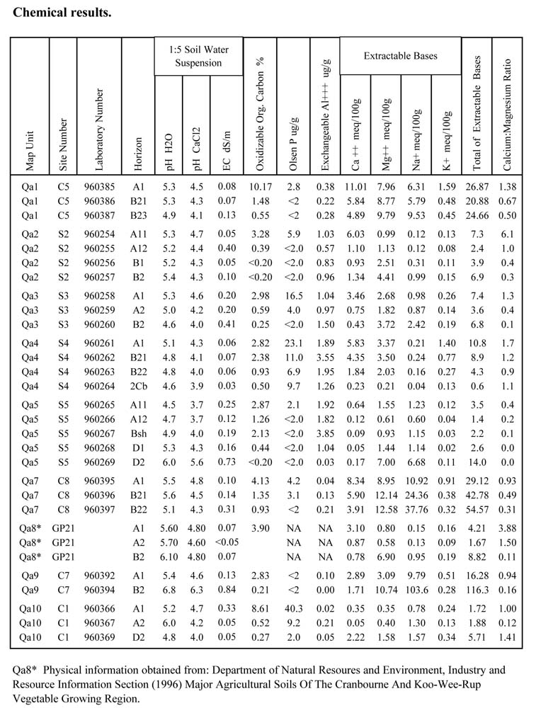
C.4.2 Chemical properties
Soil chemical analyses were carried out at the Pivotest Laboratory, Geelong.
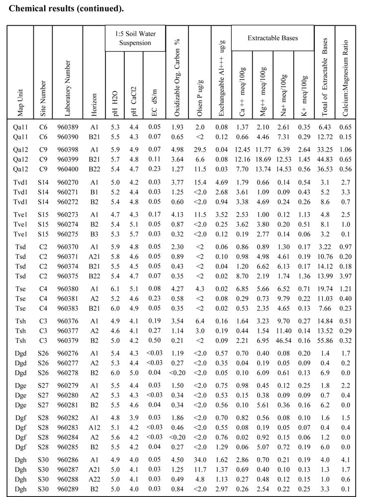
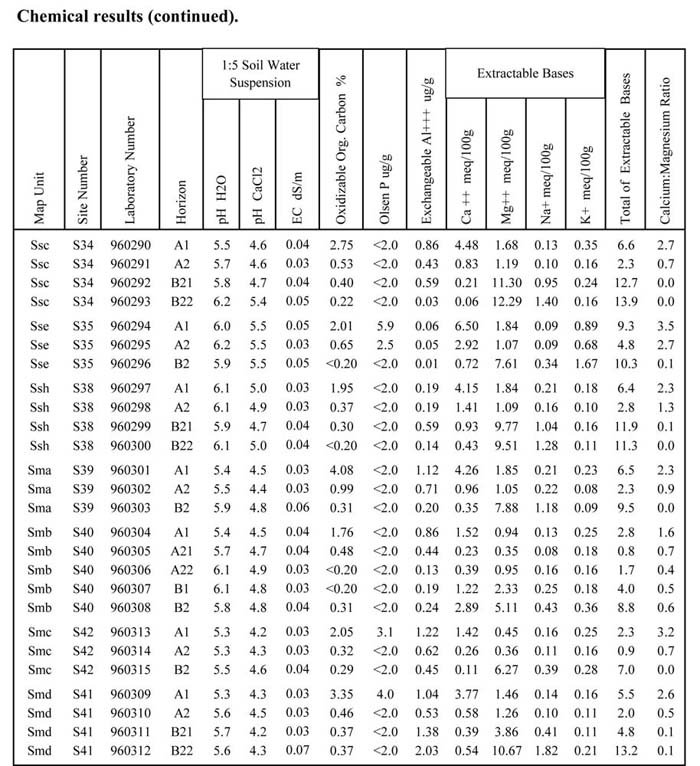
APPENDIX D. PHYSICAL AND CHEMICAL LABORATORY RESULTS
Physical results
APPENDIX E. CRITERIA USED FOR ESTABLISHING RECHARGE VALUES
| Characteristics of Very High Recharge Areas | |
| > 1000 mm/day |
| Characteristics of High Recharge Areas | |
and/or outcropping bed-rock: and/or permeability of profile: and/or clay content of clayiest layer: and/or soil type Side slopes: | < 25 cm > 10% 200 - 1000 mm/day < 25% Uniform soils: uniform sands, loamy sands, uniform loams, sandy silt loams, loams (Uc, Um, Gc) Duplex soils: red and whole coloured A2 present but not bleached high Fe2O3 content throughout B horizon > 25% |
| Characteristics of Moderate Recharge Areas | |
Outcropping bed-rock: Profile permeability: Clay content of clayiest layer: Soil type: | 25 - 100 cm 1 - 10% 50 - 200 mm/day > 25 - 35% Gradational Duplex acid, whole coloured Duplex, A2 may be present and sporadically bleached |
| Characteristics of Low-Nil Recharge Areas | |
Outcropping bed-rock: Profile permeability: Clay content of clayiest layer: Soil type: | > 100 cm = 0 < 50 mm/day > 35% Uniform clays (Uf) Uniform cracking clays (Ug) Duplex soils with conspicuously bleached A2, mottled B horizons and/or gleying characteristics. |
APPENDIX F.
Table F1 Map unit nomenclature.
Geological age | Lithology | Landform element |
| Q: Quaternary T: Tertiary K: Cretaceous P: Permian D: Devonian S: Silurian O: Ordovician C: Cambrian | a: alluvium b: basalt c: colluvium f: fans g: granite/granodiorite r: rhyodacite s: sedimentary t: tillite v: volcanics m: metamorphic | a: steep crest/ridge b: steep slope >32% c: moderately steep slope 21-32% d: moderate slope 11-20% e: gentle crest f: gentle slope 4-10% g: very gentle slope 1-3% h: drainage depression i: flat <1% l: former lake bed p: plain <1% r: rocky x: plateau 1-5: river terraces |
N.B: If differentiating geology by different characteristics such as soil or site characteristics, a number is allocated. The appropriate number goes after the geological symbol.
e.g. Tvf2 = Tertiary volcanic, remnant capping, gentle slope
GLOSSARY
The following definitions have been extracted from Charman and Murphy (1991) and McDonald et al. (1984).
Acidification:
An increase in acidity in the soil due to changes in land use, particularly agriculture. Soils that are most susceptible are generally of light texture in high rainfall areas.
Aluminium (Al) toxicity:
Plant growth in agricultural crops may be affected if aluminium levels are greater than 15 µg/g. For the purposes of this report soils with aluminium levels greater than 15 µg/g are regarded as being potentially toxic and lime may be required to promote plant growth. (State Chemistry Laboratory, pers. comm.).
Apedal:
Describes a soil in which none of the soil material occurs as peds in the moist state. Such a soil is without apparent structure and is typically massive or single-grained.
Available water for plant growth:
The amount of water in the soil that can be held between field capacity and the moisture content at which plant growth ceases.
Bleaching:
The near-white colouration of an A2 horizon which has been subject to chemical depletion as a result of soil-forming processes including eluviation. The colour is defined for all hues as having a value greater than or equal to 7 with a Chroma less than or equal to 4 on dry soils. Conspicuous bleaching means that > 80% of the horizon is bleached whereas sporadic bleaching means that < 80% of the horizon is bleached.
Consistence:
Consistence refers to the strength of cohesion and adhesion in soil. Strength will vary according to soil water status.
Dispersibility:
| Value (Emerson) | Interpretation |
| E6, E7, E8 | Very low |
| E3(1), E3(2), E4, E5 | Low |
| E3(3), E3(4) | Moderate |
| E2 | High |
| E1 | Very high |
Drainage:
Drainage is a term used to summarise local soil wetness conditions. It is affected by internal attributes which include soil structure, texture, porosity, hydraulic conductivity, water holding capacity, and external attributes such as evapotranspiration, gradient and length of slope and position in the landscape.
Categories are as follows:
Very poorly drained: Free water remains at or near the surface for most of the year. Soils are usually strongly gleyed. Typically a level or depressed site and/or a clayey subsoil.
Poorly drained: All soil horizons remain wet for several months each year. Soils are usually gleyed, strongly mottled and/or have orange or rusty linings of root channels.
Imperfectly drained: Some soil horizons remain wet for periods of several weeks. Subsoils are often mottled and may have orange or rusty linings of root channels.
Moderately well-drained: Some soils may remain wet for a week after water addition. Soils are often whole coloured, but may be mottled at depth and of medium to clayey texture.
Well-drained: No horizon remains wet for more than a few hours after water addition. Soils are usually of medium texture and not mottled.
Rapidly drained: No horizon remains wet except shortly after water addition. Soils are usually of coarse texture, or shallow, or both, and are not mottled.
Duplex soil:
A soil in which there is a sharp change in soil texture between the A and B horizons ( such as loam overlying clay).
The soil profile is dominated by the mineral fraction with a texture contrast of 1.5 soil texture groups or greater between the A and B horizons. Horizon boundaries are clear to sharp.
Electrical conductivity (EC):
A measure of the conductivity of electricity through a 1:5 soil water suspension. It is used to determine the soluble salts in the extract. The unit of electrical conductivity is the 'Siemens' and soil salinity is expressed here as decisiemens per metre at 25oC.
| Value range (dS/m) | Interpretation |
| < 0.30 | Very low |
| 0.30 - 0.53 | Low |
| 0.53 - 1.26 | Moderate |
| 1.26 - 2.50 | High |
| > 2.50 | Very high |
Flooding:
Includes overbank flow from streams and overland-channel flow along drainage depressions.
Gradational soil:
A soil in which there is a gradual change in soil texture between the A and B horizons (for example, loam over clay loam over light clay). The soil is dominated by the mineral fraction and shows more clayey texture grades on passing down the solum of such an order that the texture of each successive horizon changes gradually to that of the one below. Horizon boundaries are usually gradual or diffuse. The texture difference between consecutive horizons is less than 1.5 soil texture groups, while the range of texture throughout the solum exceeds the equivalent span of one texture group.
Gully erosion:
Erosion of soil or soft rock material by running water that forms channels larger and deeper than rills (i.e 300 mm).
Hardpan:
A hardened and/or cemented horizon, or part thereof, in the soil profile. The hardness is caused by mechanical compaction or cementation of soil particles with organic matter or with materials such as silica, sesquioxides or calcium carbonate. Such pans frequently reduce soil permeability and root penetration, and thus may give rise to plant growth and drainage problems.
Land capability assessment:
A systematic and rational method of determining the relative ability of different areas of land to sustain a specific land use under a nominated level of management without being degraded or causing any long term off-site degradation.
Land units or components:
An area of land, distinct from adjacent units or components because of specific slope, soil, or geomorphological characteristics, eg. crest, lower slope.
Land pattern/system:
An area of land, distinct from surrounding terrain, that has a specific climatic range, parent material and modal slope. Made up of a recurring sequence of land elements or components, eg. sedimentary rolling hills.
Linear shrinkage:
See Shrink/swell potential.
Mottling:
Irregular patches of colour interspersed with and different from the dominant soil colour, that vary in number and size. Mottling can indicate impeded drainage but may also be a result of parent material weathering.
Nutrient status:
Sum of exchangeable base cations (Ca, Mg, K)
| Value range (meq/100g) | Interpretation |
| < 4 | Very low |
| 4 - 8 | Low |
| 9 - 18 | Moderate |
| 19 - 30 | High |
| > 30 | Very high |
Organic matter:
All constituents of the soil arising from living matter ie. plant and microfauna detritus, fresh or decomposed. The following values for organic matter have been used in this report:
| Value range (%) | Interpretation |
| < 1 | Very low |
| 1 - 2 | Low |
| 2 - 3 | Moderate |
| > 3 | High |
| (* indicates etimated value) (organic matter % = organic C% x 1.72) | |
Parent material/rock:
The geologic material from which a soil profile develops. It may be bed-rock or unconsolidated materials including alluvium, colluvium, aeolian deposits or other sediments.
Permeability:
The characteristic of a soil, soil horizon or soil material which governs the rate at which water moves through it. It is a composite expression of soil properties and depends largely on soil texture, soil structure, the presence of compacted or dense soil horizons and the size and distribution of pores in the soil. In this study, the permeability has been measured as Ksat (saturated hydraulic conductivity). Where estimates have been made, based on the properties of the soil profile, this is clearly indicated.
| Value range (mm/day) | Interpretation |
| < 10 | Very slow |
| 10 - 100 | Slow |
| 100 - 500 | Moderate |
| 500 - 1500 | Rapid |
| 1500 - 3000 | Very rapid |
| > 3000 | Excessive |
pH (soil reaction):
A measure of the acidity or alkalinity of a soil. A pH (H2O) of 7.0 denotes neutrality, higher values indicate alkalinity and lower values indicate acidity. Strictly, it represents the negative logarithm of the hydrogen ion concentration in a specified 1:5 soil water suspension on a scale of 0 to 14. Soil pH (H2O) levels generally fall between 5.5 and 8.0 with most plants growing best in this range.
Phosphorus (P):
Deficient when less than 6 g/g.
Plasticity index:
The plasticity index of a soil is the numerical difference between the plastic limit and the liquid limit.
Potassium (K):
| K deficiency | |
| Light textures | < 80 g/g |
| Medium textures | < 110 g/g |
| Heavy textures | < 120 g/g |
| Marginal levels of K | |
| Light textures | 80-120 g/g |
| Medium textures | 110-160 g/g |
| Heavy textures | 120-180 g/g |
Rill erosion:
Erosion by small channels less than 300 mm deep which can be completely smoothed by normal cultivation.
Recharge:
Movement of surface water down into the underlying groundwaters.
Rock outcrop:
Any exposed area of rock that is inferred to be continuous with the underlying parent material.
Sheet erosion/sheet wash:
The relatively uniform removal of soil from an area without the development of conspicuous channels.
Shrink/swell potential:
The capacity of soil material to change volume with changes in moisture content, frequently measured by a laboratory assessment of the soil's linear shrinkage. It relates to the soil's content of montmorillonite type clays. High shrink swell potential in soils, such as cracking clays, can give rise to problems in earth foundations and soil conservation structures.
Categories used are:
| Shrink/swell potent. (%) | Linear shrinkage |
| 0 - 6 |
|
| 7 - 12 |
|
| 13 - 17 |
|
| 18 - 22 |
|
| > 22 |
|
Slaking:
The partial breakdown of soil aggregates in water due to the swelling of clay and the expulsion of air from pore spaces. It is a component, along with soil dispersion and soil detachment, of the process whereby soil structure is broken down in the field.
Slope:
Landform element that is neither a crest or a depression and that has an inclination greater than 1%. Slope can be broken up into the following categories:
| Value range (%) | Interpretation |
| < 1% | Level |
| 1 - 3% | Very gentle slope |
| 4 - 10% | Gentle slope |
| 11 - 20% | Moderate slope |
| 21 - 32% | Moderately steep slope |
| > 32% | Steep slope |
Soil colour:
Determined by comparison with a standard Munsell soil colour chart or its equivalent. It includes three variables of colour; hue, value and chroma.
Soil horizon:
A layer within the soil profile with distinct morphological characteristics which are different from the layers above and/or below. Horizons are more or less parallel to the land surface, except that tongues of material from one horizon may penetrate neighbouring horizons.
Soil profile:
A portion of a soil exposed in a vertical section, extending usually from the land surface to the parent material. In very general terms, a profile is made of three major layers designated A, B and C horizons. The A and B horizons are those modified by soil development. The C horizon is weathering parent material that has not yet been significantly altered by soil forming processes.
Soil texture:
The relative proportions of sand, silt and clay particles in a sample of soil. The field assessment of texture is based on the characteristics of a bolus of wetted soil moulded by hand. Six main soil texture groups are recognised
| Texture group | Approx. clay content |
2. Sandy loams 10 - 20%
3. Loams 20 - 30%
4. Clay loams 30 - 35%
5. Light clays 35 - 40%
6. Heavy clays > 45%
Unified soil group:
A soil classification system based on the identification of soil materials according to their particle size, grading, plasticity index and liquid limit. These properties have been correlated with the engineering behaviour of soils including soil compressibility and shear strength. The system is used to determine the suitability of soil materials for use in earthworks, optimal conditions for their construction, special precautions which may be needed, such as soil ameliorates, and final batter grades to be used to ensure stability.
GW: Well graded gravels, gravel-sand mixtures
GP: Poorly graded gravels, gravel-sand mixtures
GM: Silty gravels, poorly graded gravel-sand-silt mixtures
GC: Clayey gravels, poorly graded gravel-sand-clay mixtures
SW: Well graded sands
SP: Poorly graded sands
SM: Silty sands, poorly graded sand-silt mixtures
SC: Clayey sands, poorly graded sand-clay mixtures
ML: Inorganic silts and very fine sands, clayey fine sands with slight plasticity
CL: Inorganic clays of low to medium plasticity, sandy clays, silty clays
OL: Organic silts or organic silt-clays of low plasticity
MH: Inorganic silts, micaceous fine sandy or silty soils
CH: Inorganic clays of high plasticity
OH: Organic clays of moderate to
high plasticity
Pt: Peat
Uniform soil:
A soil in which there is little, if any change in soil texture between the A and B horizons (for example, loam over loam, sandy clay over silty clay). The soil is dominated by the mineral fraction and shows minimal texture difference throughout, such that no clearly defined texture boundaries are to be found. The range of texture throughout the solum is not more than the equivalent span of one soil texture group.

© State of Victoria (Agriculture Victoria) 1996 - .

This work, Victorian Resources Online, is licensed under a Creative Commons Attribution 4.0 licence. You are free to re-use the work under that licence, on the condition that you credit the State of Victoria (Agriculture Victoria) as author, indicate if changes were made and comply with the other licence terms.
The licence does not apply to ‘branding’ or some ‘images or photographs’ that may be owned by third parties. We ask you to seek prior approval to use images using the VRO feedback form. Access to higher quality images can also be provided on request.
This page was last updated on .